Plasma generator

a generator and plasma technology, applied in the direction of light sources, electrical equipment, electric discharge tubes, etc., can solve the problem of reducing the uniformity of the plasma generated at the edge of the planar antenna, and achieve the effect of uniformity of plasma and easy control of plasma distribution

Active Publication Date: 2018-10-30
JEHARA CORP
View PDF12 Cites 1 Cited by
  • Summary
  • Abstract
  • Description
  • Claims
  • Application Information

AI Technical Summary

Benefits of technology

[0009]In order to solve the above-mentioned problems, an aspect of the present invention provides a plasma generator capable of improving uniformity of plasma used in a semiconductor manufacturing process and the like and easily controlling distribution of the plasma.
[0020]According to the exemplary embodiment of the present invention, in the plasma generator, in at least one or all of a pair of electrode units which face each other in a vacuum chamber, a plurality of contact points disposed along the edge is connected to one common contact point to be connected with an impedance controller or connects a planar capacitor and an impedance controller which are provided with a predetermined width along the edge of the electrode unit. Accordingly, uniformity of the plasma can be ensured only by the control of one impedance controller and further, the distribution of the plasma can be easily controlled.

Problems solved by technology

The nonuniformity of the electromagnetic field causes a standing wave effect and thus, there is a problem in that the uniformity of the plasma generated at the edge of the planar antenna is decreased.

Method used


Image

  • Plasma generator
  • Plasma generator
  • Plasma generator

Examples


first exemplary embodiment

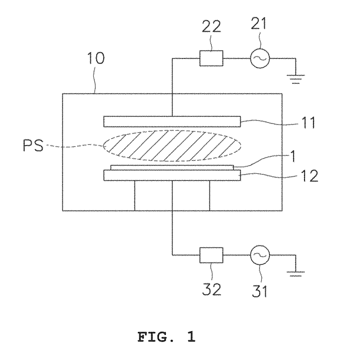
[0044]Referring to FIG. 7, a plasma generator according to a first Example includes a planar electrode constituted by a source electrode unit 110 and a bias electrode unit 120 provided in a vacuum chamber (not illustrated), and the source electrode unit 110 is connected with an RF power unit 132 with an impedance matching unit 131 interposed therebetween, and the bias electrode unit 120 is connected with a bias RF power unit 142.

[0045]Preferably, the RF power unit 132 is connected by a first power contact point p1 of the source electrode unit 110, and in this case, the first power contact point p1 is a geometric center and more preferably, positioned at an electromagnetic impedance center.

[0046]Preferably, the bias RF power unit 142 is connected by a second power contact point p2 of the bias electrode unit 120, and in this case, the second power contact point p2 is positioned in the bias electrode unit 120.

[0047]For reference, in the present invention, the ‘geometric center’ is the ...

second exemplary embodiment

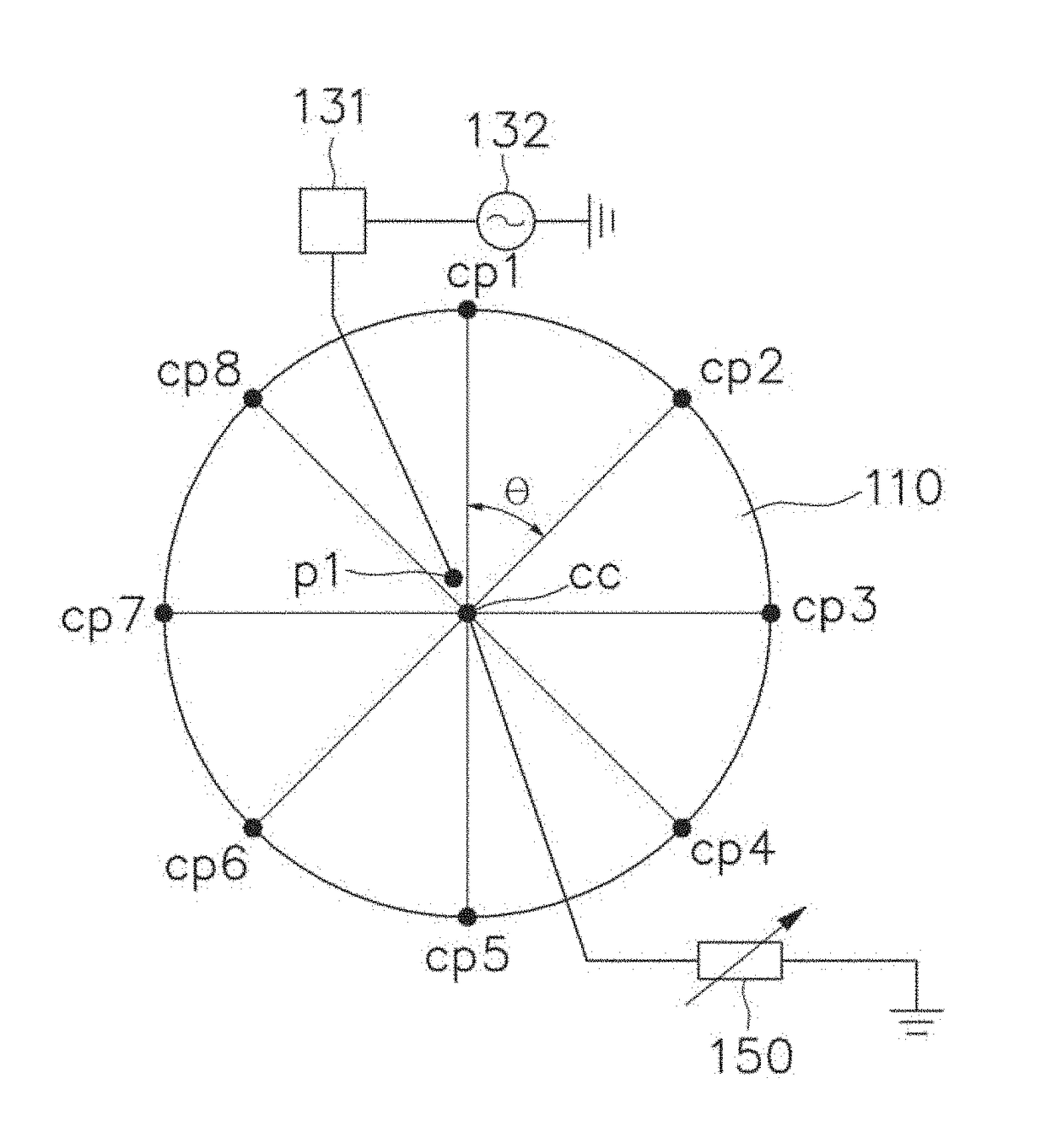
[0055]FIG. 10 is a plan configuration diagram of a plasma generator according to a second exemplary embodiment of the present invention, and the duplicated description with the first exemplary embodiment is omitted and differences will be mainly described.

[0056]The plasma generator according to the second exemplary embodiment includes a rectangular planar source electrode unit 210 and has one common contact point cc which is connected with a plurality of contact points cp1 to cp8 by respective connection lines along the edge of the source electrode unit 210 and the common contact point cc is connected with an impedance controller 250. Preferably, the common contact point cc is positioned at a geometric center or an electromagnetic impedance center of the rectangular planar source electrode unit 210, and at the geometric center, an RF power unit 232 is connected to the first power contact point p1 with an impedance matching unit 231 interposed therebetween.

[0057]In the exemplary embo...

third exemplary embodiment

[0059]FIG. 11 is a front configuration diagram of a plasma generator according to a third exemplary embodiment of the present invention, and the duplicated description with the first and second exemplary embodiments is omitted and characterized differences will be mainly described.

[0060]Referring to FIG. 11, a plasma generator according to a third exemplary embodiment of the present invention includes a source electrode unit 310 having a plurality of contact points cp disposed along the edge, an impedance controller 350 connected through a common contact point cc to which the respective contact points cp are connected through connection lines, and an RF power unit 332 which is connected through a first power contact point p1 at the geometric center or the electromagnetic impedance center of the source electrode unit 310.

[0061]Meanwhile, the bias electrode unit 320 configuring a pair of planar electrodes with the source electrode unit 310 also has a plurality of second group contact ...


PUM


Abstract

Provided is a plasma generator for improving uniformity of plasma. The plasma generator which includes a pair of source electrode unit 110 and bias electrode unit 120 disposed to face each other in a vacuum chamber and an RF power unit 132 and a bias RF power unit 142 supplying RF power to the source electrode unit 110 and the bias electrode unit 120, respectively, comprises a common contact point cc which is connected with a plurality of contact points cp disposed along the edge of the source electrode unit 110; and an impedance controller 150 which is connected with the common contact point cc to control the impedance.

Description

RELATED APPLICATIONS[0001]This application claims the priority of Korean Patent Application No. 10-2016-0079451 filed on Jun. 24, 2016, in the Korean Intellectual Property Office, the disclosure of which is incorporated herein by reference.BACKGROUND OF THE INVENTIONField of the Invention[0002]The present invention relates to a plasma generator for improving uniformity of plasma used in a semiconductor manufacturing process and the like.Description of the Related Art[0003]Plasma is the fourth material other than solid, liquid, and gas and gas of which a part is ionized, and consists of neutral particles, ions, and electrons. However, although ions and electrons are simply gathered, it is not defined as plasma, and to be in a plasma state, first, a sufficient number of “ion-electron” pairs needs to be present in a given system to enable statistic processing, and second, the whole system needs to be electrically neutralized when macroscopically viewed. Accordingly, in a general neutra...

Claims


Application Information

Patent Timeline
Patent Type & Authority Patents(United States)
IPC IPC(8): H01J7/24H05B31/26H01J37/32
CPCH01J37/32568H01J37/321H01J37/32577H01J37/32183H01J37/3211
Inventor KIM, HONGSEUB
Owner JEHARA CORP
Why Eureka
Try Eureka