Feedback gain adjusting method and device of tracking-type laser interferometer and tracking-type laser interferometer

a laser interferometer and tracking-type technology, which is applied in the direction of measuring devices, using reradiation, instruments, etc., can solve the problems of unstable optical axis tracking control system of tracking-type laser interferometer, excessive gain of control system,

Active Publication Date: 2018-11-06
MITUTOYO CORP
View PDF8 Cites 3 Cited by
  • Summary
  • Abstract
  • Description
  • Claims
  • Application Information

AI Technical Summary

Benefits of technology

[0014]In this example, an amount of time taken for the position of the return light to reach a center of the position sensitive detector from a circumference thereof due to the tracking control is referred to as a settling time, and when the settling time is more than a predetermined time, the gain for the feedback control can be increased.
[0024]According to the present invention, an optical axis tracking control system of a tracking-type laser interferometer can be stabilized by optimizing feedback gain of optical axis tracking control, without using an absolute distance between a retro reflector and a laser interferometer.

Problems solved by technology

While the rotation angle is required to control the biaxial rotation mechanism 104, the feedback control is performed using the optical axis offset, and therefore, gain of a control system may become excessive or insufficient based on an absolute distance between the retro reflector 107 and the laser interferometer 101.
However, until the absolute distance is entered, the optical axis tracking control system of the tracking-type laser interferometer is unstable.

Method used


Image

  • Feedback gain adjusting method and device of tracking-type laser interferometer and tracking-type laser interferometer
  • Feedback gain adjusting method and device of tracking-type laser interferometer and tracking-type laser interferometer
  • Feedback gain adjusting method and device of tracking-type laser interferometer and tracking-type laser interferometer

Examples


first embodiment

[0042]Hereafter, a procedural flow according to the present invention is described with reference to FIG. 6.

[0043]When determined in step S10 that the return light is returned to the position sensitive detector 102, the process advances to step S11 and saves the position P of the return light at that point and starts the tracking control in step S20.

[0044]When the return light jumps out to the opposite side of the position sensitive detector 102 in step S21, as shown in FIG. 5, in step S23, the gain is decreased to ½ by a bisection method, for example, the process is switched to the target position control of step S30, the return light is returned to the position P saved in step S11, and the tracking control is started again in step S20.

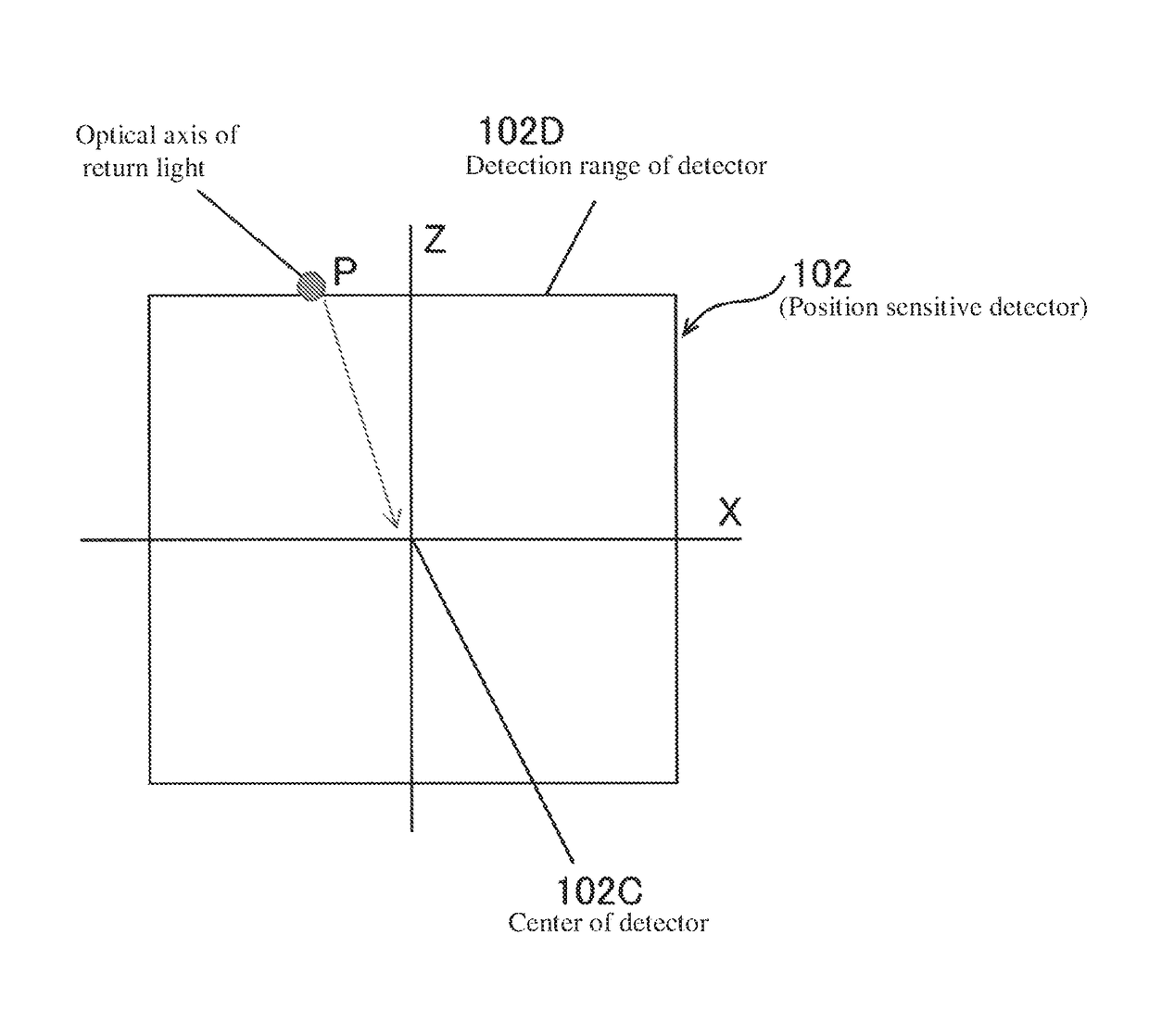
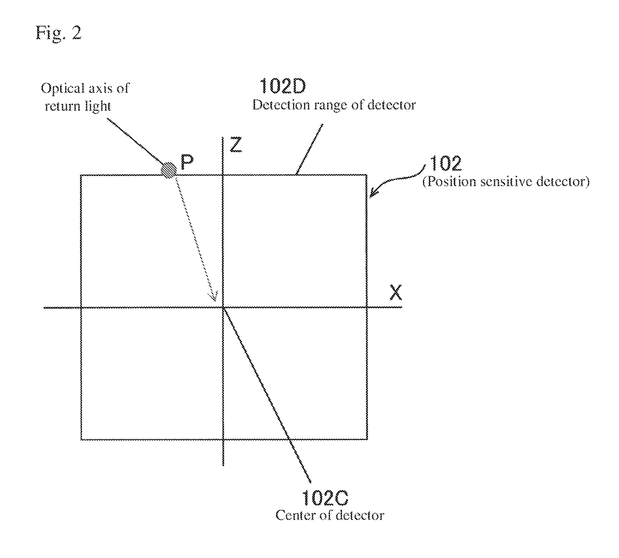
[0045]In contrast, as shown in FIG. 4, when the optical axis of the return light reaches the center 102C of the position sensitive detector 102, a time ts required to reach the center 102C (referred to as settling time) is measured in step S26. When ...

second embodiment

[0048]Next, the present invention, in which the gain adjustment is quickly performed by improving the bisection method, is described with reference to FIG. 7.

[0049]In the second embodiment, in a step S21 similar to that of the first embodiment, when a determination is made that the overshoot is large and the optical axis of the return light jumps out of the detection range 102D of the sensor 102, as shown in FIG. 5, a time tt required to jump out of the detection range 102D after switching to the tracking control (referred to as jumping out time) is measured, and when the jumping out time tt is at or below tL / 2, which is half of the settling time limit tL, for example, the process advances to step S24 and expedites convergence by decreasing the gain to ¼.

[0050]In contrast, in a step S26 similar to that of the first embodiment, when a determination is made that the optical axis fails to reach the center 102C within the settling time limit tL for example, and in step S27, when the set...


PUM


Abstract

A laser interferometer that includes a laser interferometer, an position sensitive detector detecting an offset of an optical axis of the laser interferometer, a biaxial rotator turning the laser interferometer toward an arbitrary direction, an angle sensor detecting a rotation angle of the biaxial rotator, a retro reflector reflecting reflected light in a direction parallel to incident light, and a controller performing feedback control of the biaxial rotator so as to track the retro reflector based on signals from the position sensitive detector and the angle sensor. The tracking-type laser interferometer starts tracking control when return light from the retro reflector is returned to a detection range of the position sensitive detector, and changes gain for the feedback control in accordance with a behavior for a position of the return light on the position sensitive detector due to the tracking control.

Description

CROSS-REFERENCE TO RELATED APPLICATIONS[0001]The present application claims priority under 35 U.S.C. § 119 of Japanese Application No. 2016-157922, filed on Aug. 10, 2016, the disclosure of which is expressly incorporated by reference herein in its entirety.BACKGROUND OF THE INVENTION[0002]1. Field of the Invention[0003]The present invention relates to a feedback gain adjusting method and a feedback gain adjusting device of a tracking-type laser interferometer and a tracking-type laser interferometer. Particularly, the present invention relates to a feedback gain adjusting method and a feedback gain adjusting device of a tracking-type laser interferometer and a tracking-type laser interferometer, which can stabilize an optical axis tracking control system of the tracking-type laser interferometer by optimizing feedback gain of tracking control without using an absolute distance between a retro reflector and the laser interferometer.[0004]2. Description of Related Art[0005]A tracking...

Claims


Application Information

Patent Timeline
Patent Type & Authority Patents(United States)
IPC IPC(8): G01S17/66G01S3/786
CPCG01S17/66G01S3/786
Inventor HARA, SHINICHI
Owner MITUTOYO CORP
Why Eureka
Try Eureka