Fuel injector needle valve displacement curve prediction method for jerk fuel injection system

A technology of fuel injection system and displacement curve, which is applied in the field of prediction of needle valve displacement curve of injector in pulsating fuel injection system, to achieve the effects of convenient combustion analysis, solving installation difficulties and simple working principle

Inactive Publication Date: 2017-09-05
BEIJING INSTITUTE OF TECHNOLOGYGY
View PDF2 Cites 2 Cited by
  • Summary
  • Abstract
  • Description
  • Claims
  • Application Information

AI Technical Summary

Problems solved by technology

There is no relevant scientific and technical literature to give the corresponding relationship between the movement of the injector needle valve and the fluctuation of fuel pressure in the pulse fuel injection system

Method used


Image

  • Fuel injector needle valve displacement curve prediction method for jerk fuel injection system
  • Fuel injector needle valve displacement curve prediction method for jerk fuel injection system
  • Fuel injector needle valve displacement curve prediction method for jerk fuel injection system

Examples


Embodiment Construction

[0025] The present invention will be described in detail below with reference to the accompanying drawings and examples.

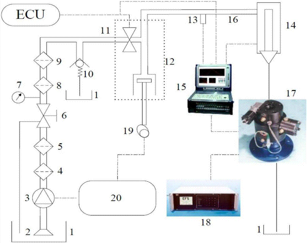
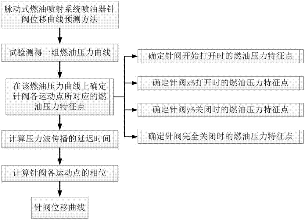
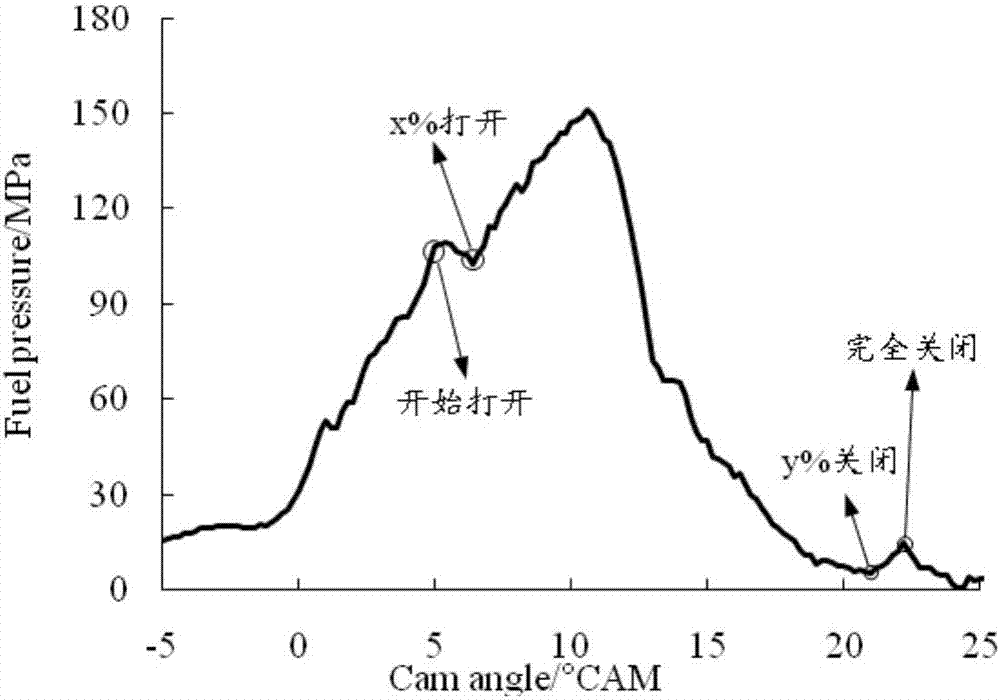
[0026] The motion state of the injector needle valve mainly includes two steady states of normally closed and normally open, and two transient states of open and closed. When the needle valve is normally closed and normally open, its displacement is 0 and the maximum lift respectively, so the key is to determine the phase and displacement corresponding to the two transient states of the needle valve opening and closing. Since the time it takes for the needle valve to open and close is extremely short, it can be assumed that both opening and closing are a constant speed process. In addition, the maximum lift of the needle valve is known and can be provided by the manufacturer. Therefore, it is only necessary to determine the phases when the needle valve begins to open, x% open, y% close, and fully closed, and then calculate the delay of the pressure wave t...


PUM


Abstract

The invention provides a fuel injector needle valve displacement curve prediction method for a jerk fuel injection system. According to the motion characteristics of a fuel injector needle valve and the pressure fluctuation characteristics of a fuel pressure curve, the opening and closing phases of the needle valve are determined, and the delay of pressure waves is then calculated to obtain a displacement curve of the needle valve. A needle vale displacement sensor can be replaced, the problems of the displacement sensor, such as difficulty in installation and high cost, are solved, and the objectives of combustion analysis, fault diagnosis and feedback control carried out on an engine are achieved.

Description

technical field [0001] The invention relates to the fields of engine combustion analysis, fault diagnosis and feedback control, in particular to a method for predicting a needle valve displacement curve of a pulsating fuel injection system. Background technique [0002] The pulsating fuel injection system requires less modification to the engine, and has the characteristics of flexible and controllable fuel injection volume and fuel injection timing. The problem of leakage has obvious advantages compared to the high-pressure common rail fuel system. In addition, its system performance is reliable and its life is long. Therefore, the pulsating fuel injection system is widely used in medium and heavy-duty diesel engines. [0003] At present, the technical research on the pulsating fuel injection system mainly focuses on the design of the overall structure and sealing structure of the pulsating fuel injection system, the design of the electronic control unit, the optimization...

Claims


Application Information

Patent Timeline
Patent Type & Authority Applications(China)
IPC IPC(8): G06F17/50
CPCG06F30/17G06F30/20
Inventor 刘福水康宁黎一锴王沛花阳
Owner BEIJING INSTITUTE OF TECHNOLOGYGY
Why Eureka
Try Eureka