Exhaust gas recirculation system for internal combustion engine

a technology of exhaust gas recirculation and internal combustion engine, which is applied in the direction of charge feed system, electric control, combustion engine, etc., can solve the problems of excessive change of intake gas temperature, difficulty in causing the temperature of intake gas, and in terms of control gain setting, etc., to increase the flow rate of egr gas, and increase the effect of cooling efficiency

Active Publication Date: 2019-06-27
TOYOTA JIDOSHA KK
View PDF4 Cites 2 Cited by
  • Summary
  • Abstract
  • Description
  • Claims
  • Application Information

AI Technical Summary

Benefits of technology

[0015]The control device may be configured to more increase the amount of change of the cooling efficiency when an EGR ratio is lower.
[0016]According to the exhaust gas recirculation system for an internal combustion engine of the present disclosure, the cooling efficiency of the EGR cooling system is determined by the feedback control performed such that the temperature of the intake gas suctioned into the cylinder of the internal combustion engine is caused to approach the target intake gas temperature. Also, the greater the flow rate of the EGR gas is, the greater the effects of the temperatu...

Problems solved by technology

However, even if the temperature of the EGR gas is caused to approach the target EGR gas temperature, it is difficult to cause the temperature of intake gas that is a mixed gas of fresh air and the EGR gas to approach a target intake gas temperature.
However, in this kind of feedback control, there is a problem in terms of the setting of a control gain.
If, on the other hand, a control gain that is optimum when the flow rate of the EGR gas i...

Method used


Image

  • Exhaust gas recirculation system for internal combustion engine
  • Exhaust gas recirculation system for internal combustion engine
  • Exhaust gas recirculation system for internal combustion engine

Examples


first embodiment

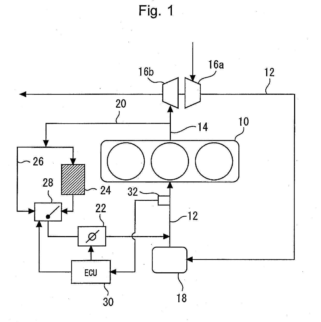
[0024]FIG. 1 is a diagram that illustrates the configuration of an engine system to which an exhaust gas recirculation system according to the first embodiment is applied. As shown in FIG. 1, the system according to the present embodiment is provided with an internal combustion engine 10. The internal combustion engine 10 is configured as an in-line three-cylinder diesel engine that is mounted on a mobile object, such as a vehicle. However, the type of the internal combustion engine 10 and the number and arrangement of cylinders thereof are not limited to the foregoing. An intake air passage 12 and an exhaust gas passage 14 communicate with each cylinder 10.

[0025]A compressor 16a of a supercharger (more specifically, turbo-supercharger) is installed in the intake air passage 12. A turbine 16 is installed in the exhaust gas passage 14. The compressor 16a is driven by the rotation of the turbine 16b. A water-cooled intercooler 18 is installed in a portion of the intake air passage 12 ...

second embodiment

[0042]In the present embodiment, a description of parts common to those in the first embodiment will be omitted.

[0043]FIG. 5 is a diagram that illustrates the configuration of an engine system to which the exhaust gas recirculation system according to the second embodiment is applied. According to the configuration of the system of the present embodiment, control valves 40 and 42 are provided instead of the EGR valve 22 and the flow-rate-ratio adjustment valve 28 according to the first embodiment. The control valve 40 is arranged at a portion of the EGR passage 20 located on the downstream side of a branch portion of the bypass passage 26 and on the upstream side of the EGR cooler 24. The control valve 40 can adjust the EGR gas flow rate GegrC concerning the EGR gas passing through the EGR cooler 24. Moreover, the control valve 42 is arranged at some point in the bypass passage 26, and can adjust the EGR gas flow rate GegrCbp concerning the EGR gas passing through the bypass passage...


PUM


Abstract

An exhaust gas recirculation system for an internal combustion engine is provided. The exhaust gas recirculation system includes: an EGR passage configured to connect an exhaust gas passage of the internal combustion engine with an intake air passage; an EGR cooling system arranged at the EGR passage; and a control device configured to control the EGR cooling system. The control device is configured to provide feedback control of the cooling efficiency of the EGR cooling system to cause the temperature of intake gas suctioned into a cylinder of the internal combustion engine to approach a target intake gas temperature. The control device is configured to more increase the amount of change of the cooling efficiency when the flow rate of EGR gas recirculated is less.

Description

CROSS-REFERENCE TO RELATED APPLICATION[0001]This application is based on and claims the benefit of Japanese Patent Application No. 2017-251210, filed on Dec. 27, 2017, which is incorporated by reference herein in its entirety.BACKGROUNDTechnical Field[0002]The present disclosure relates to an exhaust gas recirculation system for an internal combustion engine in which an exhaust gas recirculation (EGR) operation to recirculate, into an intake system, a part of the gas discharged from the internal combustion engine.Background Art[0003]For example, JP 2001-041110 A discloses an EGR device with an EGR cooler. This EGR device is provided with a flow-rate-ratio adjustment valve configured to adjust the flow rate ratio of the flow rate of EGR gas passing through the EGR cooler and the flow rate of EGR gas that does not pass through the EGR cooler. Moreover, this EGR device detects the temperature of EGR gas after the EGR gas that has passed through the EGR cooler is mixed with the EGR gas ...

Claims


Application Information

Patent Timeline
IPC IPC(8): F02M26/33F02M26/17F02M26/47F02M26/26
CPCF02M26/33F02M26/17F02M26/47F02M26/26F02M26/25F02D41/0052F02D2041/0067F02D2021/083F02D41/0047F02D2200/0414F02D41/0072F02D41/0077Y02T10/40
Inventor MORISHIMA, AKINORIIBUKI, TAKUGOTO, TAKESHIHASEGAWA, RYO
Owner TOYOTA JIDOSHA KK
Why Eureka
Try Eureka