
Electronic control device

a technology of electronic control device and stepup circuit, which is applied in the direction of dc-dc conversion, power conversion system, instruments, etc., can solve the problems of circuit malfunction, current cannot be suppressed, circuit malfunction, etc., and achieve the effect of reducing the effect of voltage changes in a peripheral circuit and reducing the voltage changes generated by electromagnetic induction caused by rapid current fluctuation generated when stepping up is started and stopped

Active Publication Date: 2018-11-06
HITACHI ASTEMO LTD
View PDF17 Cites 0 Cited by
  • Summary
  • Abstract
  • Description
  • Claims
  • Application Information

AI Technical Summary

Benefits of technology

The patent aims to reduce the effects of voltage changes caused by rapid current fluctuations when starting and stopping an electromagnetic induction process. This invention helps to minimize the impact of these changes on peripheral circuits.

Problems solved by technology

Since the voltage changes in the signal lines are not intended, there is a possibility that the voltage changes cause a circuit malfunction.
In this case, since the current exceeds the current upper limit threshold of a target current value, the current cannot be suppressed.
Since the voltage changes in the signal lines are not intended, there is a possibility that the voltage changes cause a circuit malfunction.

Method used


Image

  • Electronic control device
  • Electronic control device
  • Electronic control device

Examples


Embodiment Construction

[0018]Embodiments of the present invention will be described in detail below with reference to the drawings.

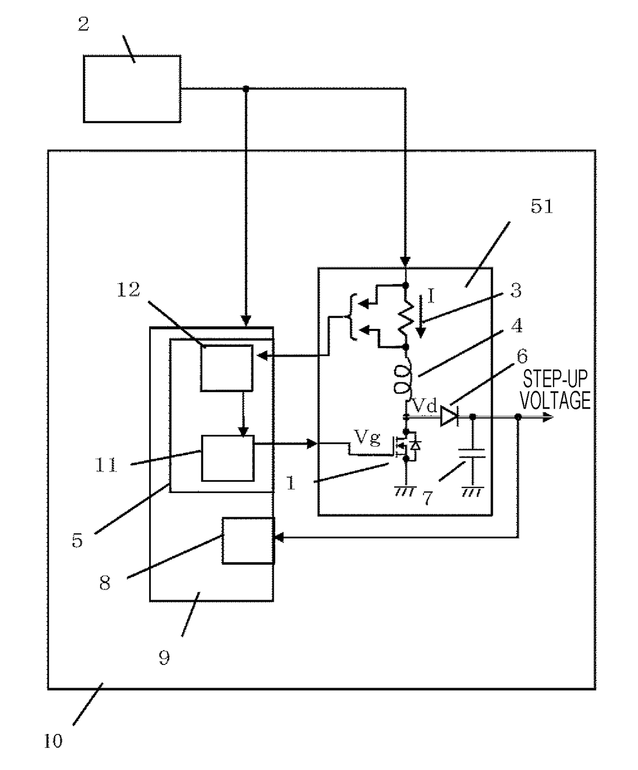
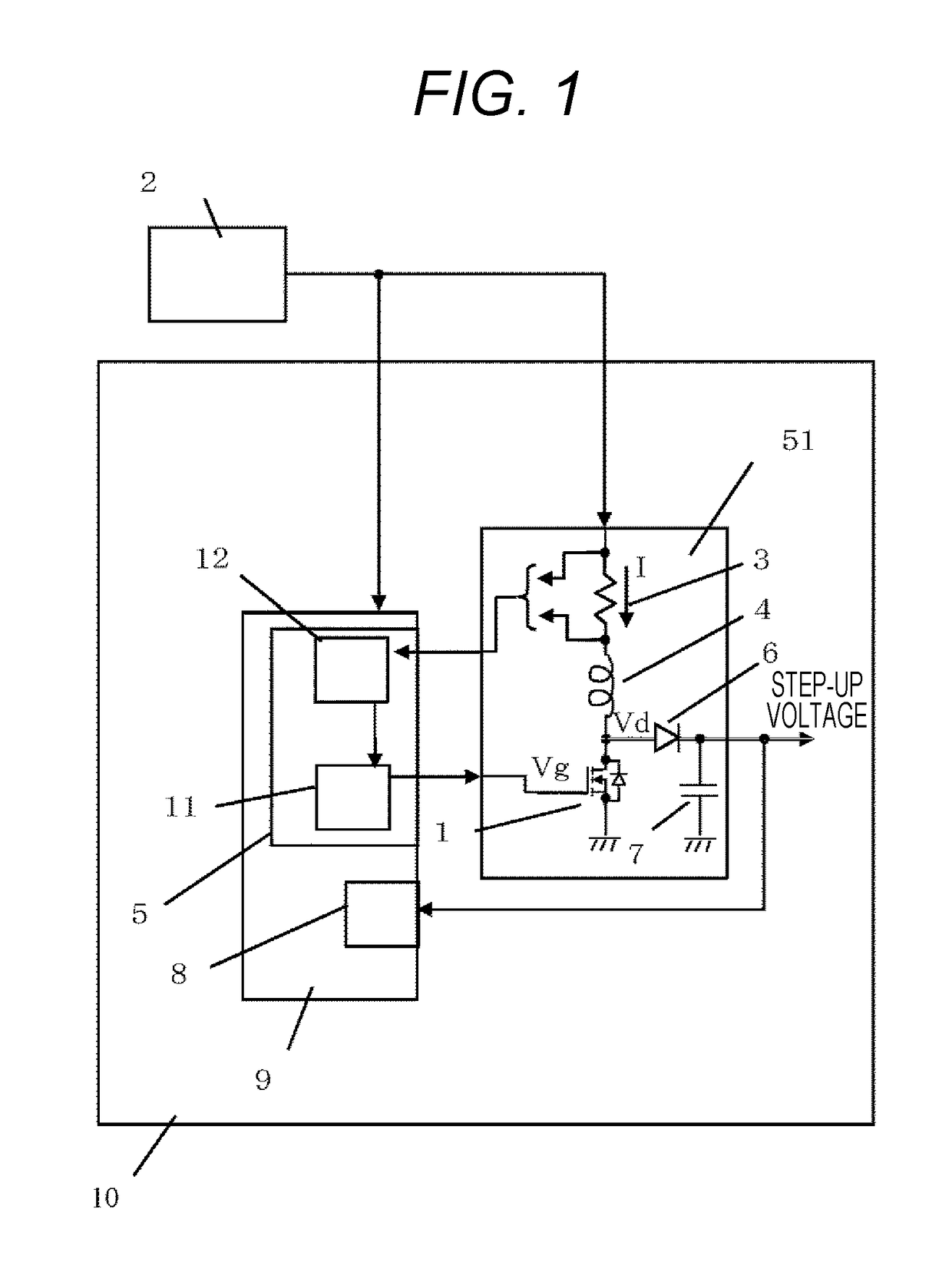
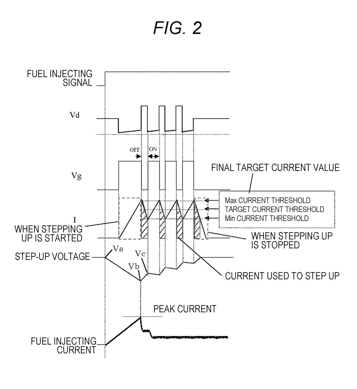
[0019]A structure of a step-up circuit of a fuel injector driving circuit 10 according to the present embodiment is described with reference to FIG. 1. When a gate voltage Vg of a step-up driver 1 is turned ON, a current I is flown from a battery 2 to a GND via a shunt resistor 3, a step-up coil 4, and the step-up driver 1. The current at this time is detected by a voltage monitor 12 included in a step-up circuit driving unit 5 in a driver IC 9 as voltages on both sides of the shunt resistor 3. When the Max current threshold which has been set is detected, a step-up gate control circuit 11 turns OFF the step-up driver 1. At this time, an electromotive force of the step-up coil 4 flows the current I to a step-up diode 6. A step-up capacitor 7 temporarily stores the current flown into the diode. Next, when the current flown into the shunt resistor 3 is reduced, the step-up drive...


PUM


Abstract

In a step-up circuit, which is an electronic control device, changes in current caused by a current rise when stepping up is started and a current drop when stepping up is stopped generate magnetic induction noise due to fluctuations in the electromagnetic induction voltage in signal lines around the step-up circuit. The present invention is a step-up circuit for stepping up by current control, wherein the step-up circuit is provided with a plurality of target current values for retaining a step-up current so that the current is raised in a stepwise manner when stepping up is started and dropped in a stepwise manner when stepping up is stopped. The present invention reduces electromagnetic induction noise generated by the changes in current when stepping up is started and when stepping up is stopped.

Description

TECHNICAL FIELD[0001]The present invention relates to a step-up circuit in an electronic control device.BACKGROUND ART[0002]JP 2013-253530 A shows a background art.[0003]In this patent literature, a step-up converter in a fuel injector repeats ON / OFF of a current between an upper and lower limit values of a threshold so as to maintain an average current constant by switching control. Also, when the current value reaches a certain value, the average current is maintained to be constant. Stepping up from start to the above certain value is performed at one time, not in a stepwise manner. According to the above, the higher the average current value to be maintained constant is, the larger the current fluctuation at the time when stepping up is started is. Accordingly, voltage changes in signal lines around the circuit is generated by electromagnetic induction. Also, when stepping up is stopped, the larger the average current value to be maintained constant is, the larger the current dr...

Claims


Application Information

Patent Timeline
Patent Type & Authority Patents(United States)
IPC IPC(8): G05F1/10G05F3/02H02M3/07H03K5/19
CPCH03K5/19H02M3/07H02M3/155
Inventor TSUKIO, KOICHI
Owner HITACHI ASTEMO LTD
Learn More