Balloon catheter and methods of use thereof

a balloon catheter and balloon technology, applied in the field of balloon catheters, can solve the problems of complex operation of the mechanism to move the inner conduit as combined with the intussusceptible balloon, and the difficulty of construction and operation,

Inactive Publication Date: 2018-11-13
ANGIOSLIDE
View PDF178 Cites 11 Cited by
  • Summary
  • Abstract
  • Description
  • Claims
  • Application Information

AI Technical Summary

Benefits of technology

[0043]There is therefore provided, in accordance with an embodiment of the catheters of the present application, a balloon catheter including a catheter shaft, an inflatable balloon attached to the catheter shaft and an open sleeve having a proximal end sealingly attached to the catheter shaft and an open distal end, the sleeve surrounds at least part of the balloon. The sleeve and the balloon are arranged such that inflating the balloon expands the sleeve into an expanded state and deflating the balloon when the sleeve is in the expanded state forms an open cavity between the sleeve and the deflated balloon and creates suction to capture and retain debris within the cavity.
[0048]Furthermore, in accordance with an embodiment of the catheters of the present application, the catheter shaft includes at least three fluidically separate hollow passages therein. The hollow passages include a first hollow passage for inserting a guide wire therethrough, a second hollow passage for inserting inflation fluid into the balloon and for withdrawing inflation fluid from the balloon, and a third hollow passage fluidically connected to the cavity between the balloon and the sleeve. Suction from an external suction source may be applied to the cavity through the third hollow passage to assist the capturing and retaining of the debris within the cavity or within the third hollow passage.
[0066]Furthermore, in accordance with an embodiment of the catheters of the present application, both the sleeve and the balloon are folded around a portion of the catheter shaft prior to inflating the balloon to reduce the crossing profile of the catheter.
[0067]Furthermore, in accordance with an embodiment of the catheters of the present application, the balloon is folded around a portion of the catheter shaft prior to inflating the balloon, and wherein the sleeve is folded over the balloon to reduce the crossing profile of the catheter.
[0079]Furthermore, in accordance with an embodiment of the method of the present application, the catheter shaft includes a hollow passage fluidically connected to the cavity formed between the balloon and the sleeve and the method also includes the step of applying suction to the cavity from an external suction source through the hollow passage to assist the capturing and the retaining of debris within the cavity of the catheter.
[0081]Furthermore, in accordance with an embodiment of the method of the present application, the catheter shaft comprises at least three fluidically separate hollow passages therein. The first hollow passage has a first opening disposed on the catheter shaft for inserting a guide wire there through and a second opening disposed at the distal end of the catheter shaft for allowing the guide wire to exit through the second opening. The catheter shaft includes a second hollow passage for inserting and withdrawing inflation fluid into and from the balloon, respectively, and a third hollow passage fluidically connected to the cavity between the balloon and the sleeve through the third hollow passage. The method also includes the step of applying suction from an external suction source to the cavity through the third hollow passage, to assist the capturing and the retaining of the debris within the cavity or within the third hollow passage.

Problems solved by technology

While sealing gaskets are well known in the art their use may pose several technical difficulties, due mainly to the fact that the implementation of sealing gaskets may require expensive and time consuming construction techniques as well as the use of time consuming and expensive testing and quality control procedures.
This is especially challenging when the diameters of inner conduit and of the necessary gaskets are relatively small.
While the cavity forming intussuscepting balloons are quite efficient for trapping debris and / or particulate matter or secretions from the treated site, the construction of a movable inner conduit that slides within an outer conduit and the operation of mechanisms to move the inner conduit as combined with an intussuscepting balloon are fairly complex and require expertise to construct and to operate.
In particular rapid exchange (monorail) catheters with intussuscepting balloons are not simple to construct.
However, such sleeve devices are separate from the debris collecting catheter, require the handling and operating of two separate devices (a sleeve collecting device and a separate debris collecting catheter which is separate from the sleeve device that are longitudinally or axially freely movable relative to each other).

Method used


Image

  • Balloon catheter and methods of use thereof
  • Balloon catheter and methods of use thereof
  • Balloon catheter and methods of use thereof

Examples


Embodiment Construction

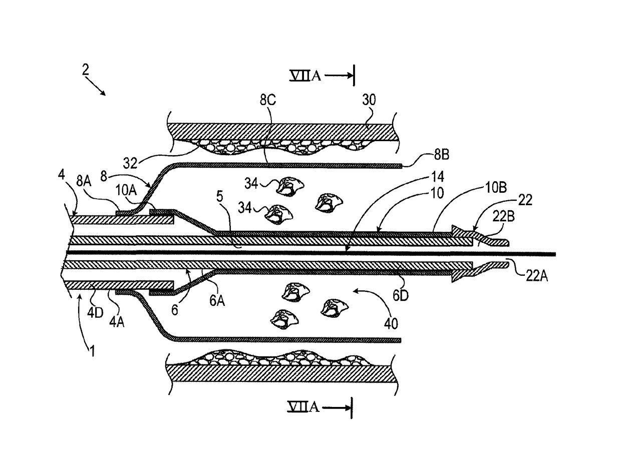
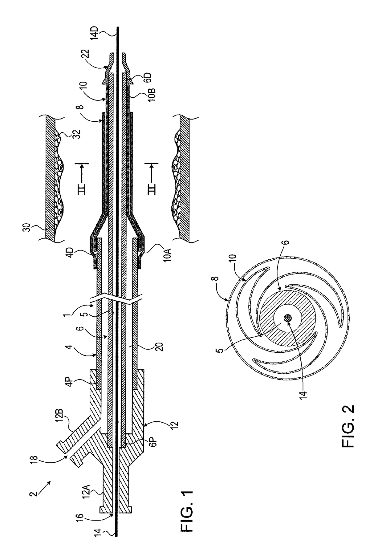
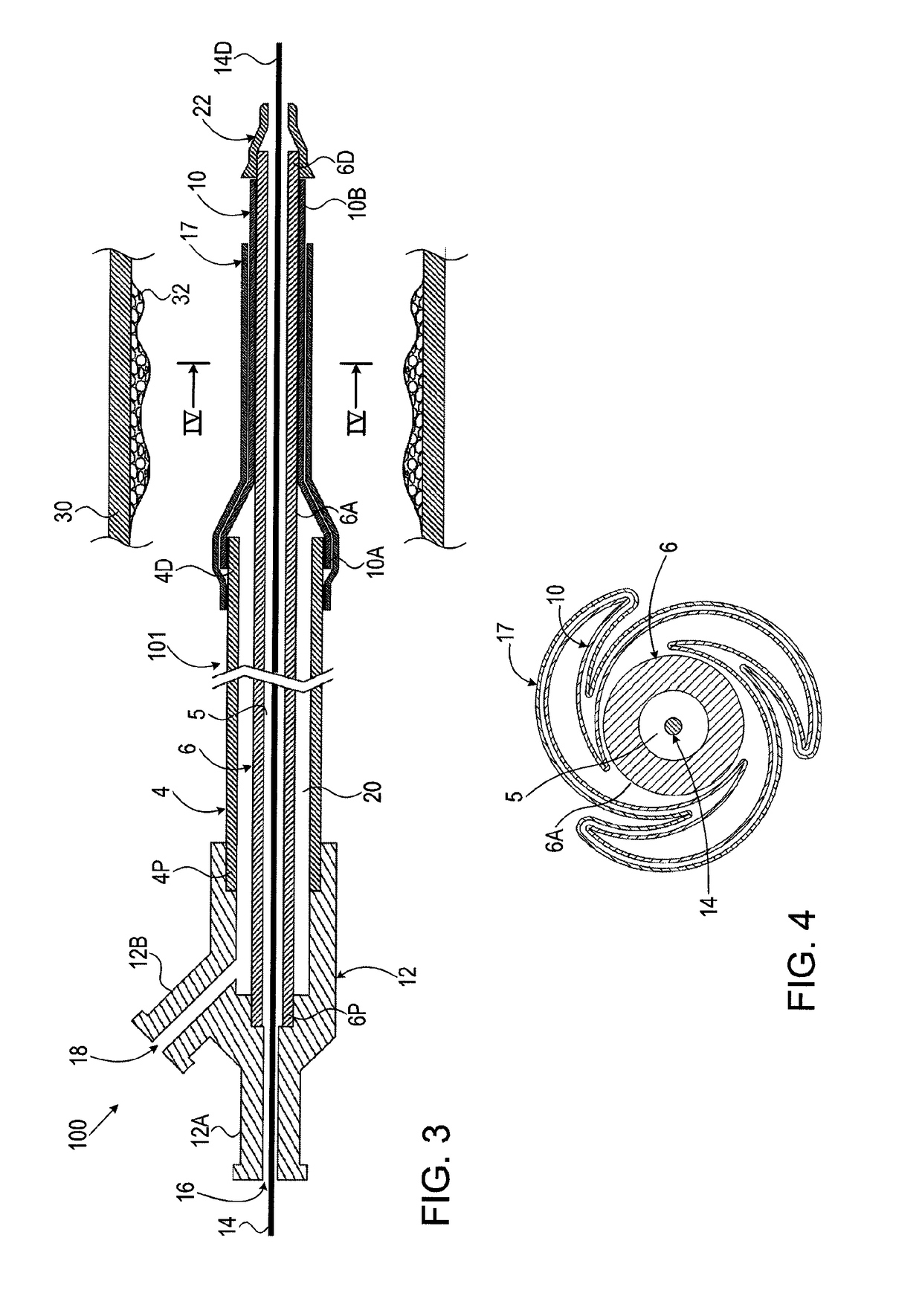
[0086]The device is herein described, by way of example only, with reference to the accompanying drawings. With specific reference now to the drawings in detail, it is stressed that the particulars shown are by way of example and for purposes of illustrative discussion of the preferred embodiments of the exemplary systems only and are presented in the cause of providing what is believed to be a useful and readily understood description of the principles and conceptual aspects of the invention. In this regard, no attempt is made to show structural details of the invention in more detail than is necessary for a fundamental understanding of the invention, the description taken with the drawings making apparent to those skilled in the art how several forms of the invention may be embodied in practice and how to make and use the embodiments.

[0087]For brevity, some explicit combinations of various features are not explicitly illustrated in the figures and / or described. It is now disclosed...


PUM


Abstract

A balloon catheter including a shaft and an inflatable balloon attached to the shaft, the catheter includes an open sleeve having a proximal end sealingly attached to the catheter shaft and an open distal end. The sleeve surrounds at least part of the balloon. The sleeve and the balloon are arranged such that inflating the balloon expands the sleeve into an expanded state and deflating the balloon when the sleeve is in the expanded state forms an open cavity between the sleeve and the deflated balloon and creates suction to capture and retain debris within the cavity.

Description

CROSS-REFERENCE TO RELATED APPLICATIONS[0001]This application is a continuation of International Application No. PCT / IL2013 / 000089, which has an international filing date of Dec. 4, 2013, and which claims the benefit of U.S. Provisional Patent Application No. 61 / 732,944, filed on Dec. 4, 2012, the disclosure of which is incorporated herein by reference.FIELD OF THE INVENTION[0002]This invention relates in general to the field of medical catheters having inflatable balloons and more particularly to catheters having a balloon with an open sleeve.BACKGROUND OF THE INVENTION[0003]Catheters are used in various interventional procedures for delivering therapeutic means to a treated site (e.g., body organ or passageway such as blood vessels). In many cases, a catheter with a small distal inflatable balloon is guided to the treated site. Once the balloon is in place it is inflated by the operator for affixing it in place, for expanding a blocked vessel, for placing treatment means (e.g., st...

Claims


Application Information

Patent Timeline
Patent Type & Authority Patents(United States)
IPC IPC(8): A61M25/10A61M25/00A61F2/958A61M1/00A61B17/221A61B17/22A61M25/01
CPCA61B17/221A61M25/104A61B17/22032A61F2/958A61M1/0009A61M1/0011A61M1/0039A61M1/0045A61M1/0066A61M1/0072A61M25/0074A61M25/0082A61M25/1006A61M25/1011A61B2017/22052A61B2017/22054A61B2017/22061A61B2017/22065A61B2017/22079A61F2002/9583A61M2025/0004A61M2025/0024A61M2025/0039A61M2025/0183A61M2025/105A61M2025/109A61M2025/1013A61M2025/1015A61M2025/1052A61M2025/1081A61M2025/1086A61M2025/1093A61M2202/0007A61M2202/0014A61M2205/32A61B17/22031A61B2017/2215A61B2017/22035A61B2017/22038A61B2017/22051A61M1/68A61M1/67A61M1/76A61M1/80A61M1/82A61M1/7415
Inventor FEIG, ROYMEISTER, GALBARASH, ALEXBERNSTEIN, GIL
Owner ANGIOSLIDE
Why Eureka
Try Eureka