Universal catheter tip and methods of manufacturing

a technology of universal catheters and manufacturing methods, applied in the field of universal catheter tip and manufacturing methods, can solve the problems of large inventory of devices that may be expensive and difficult to maintain, and achieve the effects of reducing the crossing profile, high burst pressure, and convenient adjustmen

Inactive Publication Date: 2020-07-09
SANFORD HEALTH
View PDF4 Cites 0 Cited by
  • Summary
  • Abstract
  • Description
  • Claims
  • Application Information

AI Technical Summary

Benefits of technology

[0003]The present disclosure provides a catheter tip that may be advantageously adjustable for use with guide wires of varying diameters. Such catheter tips may have a length ranging from roughly 4 cm to 60 cm and may have a diameter ranging from 4 French to 25 French depending on the particular device being delivered in vivo. The French size of the catheter refers to the outer diameter that is also termed the catheter's “crossing profile.” Reducing the crossing profile may allow the catheter to cross narrow lesions and to enter smaller blood vessels. The material of the catheter tip may be flexible, kink resistant, atraumatic, and torquable. The material of the catheter tip may be silicone, polyurethane, nylon, or Pebax among other materials. Catheters and tips of the present disclosure may be lined by materials that are hemocompatible, lubricious, non-thrombogenic, and / or sometimes radiopaque. The inner liner materials may be polytetrafluoroethylene (PTFE), polyimide, or high density polyethylene, for example. The mechanical properties of such a catheter tip may include high burst pressure, high tensile strength and compression resistance, high modulus of elasticity and low coefficient of friction. Forming techniques for catheter tips of the present disclosures can include coated extrusions, co-extrusions, coil-reinforced or braid-reinforced composites that may further include an inner lubricious layer, reinforcement layer and an outer jacket layer. The coil- or braid-reinforced metal layers may provide tensile strength, while the polymer layer may provide lubricity and flexibility. The catheter tips are bonded to the catheter in such a way so as to minimize risk of separation from one another during the procedure, because a tip that separates from the catheter can create a situation where blood flow is blocked to a major organ.
[0006]In a third aspect, the present disclosure provides a method that includes: (a) applying a force to the second end of the catheter tip according to the first aspect thereby increasing a diameter of the expandable opening at the first end of the catheter tip, (b) positioning a guide wire through the expandable opening, (c) removing the force from the second end of the catheter tip thereby decreasing the diameter of the expandable opening, and (d) advancing the catheter tip along the guide wire to a target lumen.

Problems solved by technology

As a result, the various sized guide wires require a large inventory of devices that may be expensive and difficult to maintain.

Method used


Image

  • Universal catheter tip and methods of manufacturing
  • Universal catheter tip and methods of manufacturing
  • Universal catheter tip and methods of manufacturing

Examples


Embodiment Construction

[0017]The description of the different advantageous arrangements are presented for purposes of illustration and description, and are intended to be exhaustive or limited to the examples in the form disclosed. Many modifications and variations will be apparent to those of ordinary skill in the art. Further, different examples may provide different advantages as compared to other advantageous examples. The example or examples selected are chosen and described in order to best explain the principles of the examples, the practical application, and to enable others of ordinary skill in the art to understand the disclosure for various examples with various modifications as are suited to the particular use contemplated.

[0018]As used herein, with respect to measurements, “about” means+ / −5%.

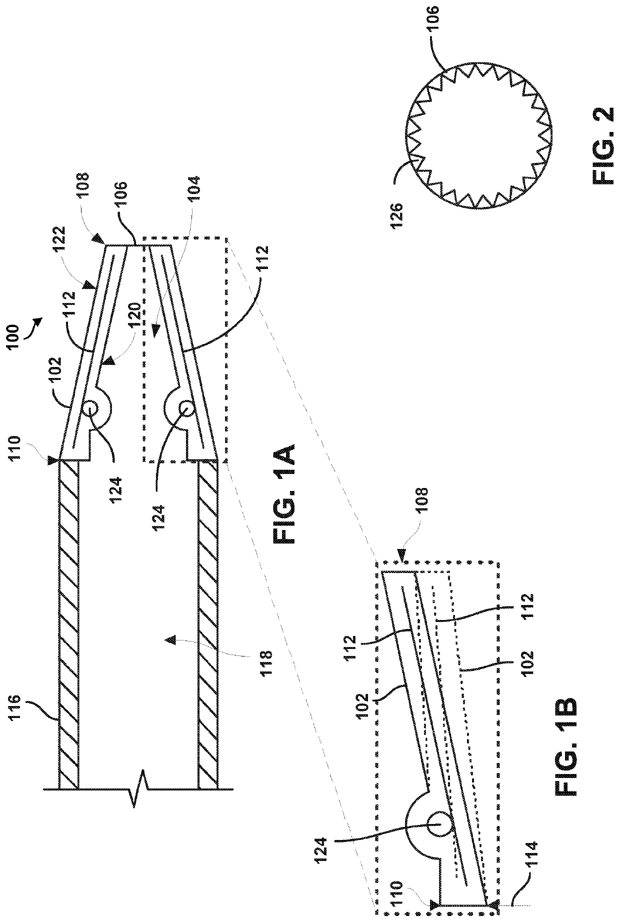
[0019]As used herein, “coupled” means associated directly, as well as indirectly. For example, a member A may be directly associated with a member B, or may be indirectly associated therewith, e.g., via a...


PUM


Abstract

The present disclosure provides a catheter tip (100) including a flexible housing (102) defining a cavity (104) extending between an expandable opening (106) arranged at a first end (108) of the catheter tip and a second end (110) of the catheter tip. The catheter tip further includes a plurality of pivotable arms (112) coupled to and extending longitudinally along the flexible housing. The plurality of pivotable arms are arranged to taper inwardly at the first end of the catheter tip toward a longitudinal axis of the flexible housing. The expandable opening is configured to increase in diameter from a first position to a second position in response to application of an external force to the second end of the flexible housing.

Description

RELATED APPLICATIONS[0001]This application claims the benefit of priority to U.S. Provisional Application No. 62 / 552,168 entitled “Universal Catheter Tip and Methods of Manufacturing,” filed on Aug. 30, 2017, the contents of which are hereby incorporated by reference in its entirety.BACKGROUND THE INVENTION[0002]The current state of the art for devices that are advanced via guide wires to various arterial configurations requires a separate device for each diameter of guide wire. For example, a larger guide wire having a diameter of 0.9562 mm may be used for certain aspects of a given procedure, while a smaller guide wire having a diameter of 0.254 mm may be used for different aspects of the same procedure. Using current devices, a different catheter having a different size tip would need to be used for each guide wire size. For example, the 0.9652 mm diameter tip cannot be used on the 0.254 mm guide wire, because there would be a ridge created that would catch on lesions that may al...

Claims


Application Information

Patent Timeline
Patent Type & Authority Applications(United States)
IPC IPC(8): A61M25/00A61F2/07A61B17/12A61B17/3205A61F2/95
CPCA61M25/0074A61B17/32056A61B2017/00292A61M25/001A61M2025/0079A61F2/95A61B17/12022A61F2/07A61M25/0069A61B17/3468
Inventor KELLY, PATRICK W.
Owner SANFORD HEALTH
Why Eureka
Try Eureka