Fluidic artificial muscle actuator and swaging process therefor

a technology of artificial muscles and actuators, applied in the field of actuators, can solve problems such as inflation and expansion of bladders, and achieve the effects of high bursting pressure, simple and robust connection, and high tensile strength

Active Publication Date: 2012-11-13
INNOVITAL LLC +1
View PDF4 Cites 7 Cited by
  • Summary
  • Abstract
  • Description
  • Claims
  • Application Information

AI Technical Summary

Benefits of technology

[0010]A new end fitting design and manufacturing technique has been invented that produces a simple and robust connection with high tensile strength, high bursting pressures and long fatigue life. This process uses a conical steel die 23 to swage a thin walled tube around the specially designed end fittings, braided sleeve, and bladder. The plastic deformation that occurs during the swaging process is axisymmetric and serves to clamp the sleeve and tube to the end fitting. Additionally, adhesive may be spread onto the outer surfaces of the end fittings themselves and / or to the section of the sleeve and / or bladder that comes into contact with the end fittings before the swaging assembly process is begun, during assembly, or after its completion to increase the mechanical strength of the actuator and to ensure a pressure tight seal.
[0011]The invented process is simple and low cost to implement. Additionally, the quality and reliability of the finished device are high, so the reduced manufacturing costs do not come at the expense of actuator performance. The object of this invention is therefore to establish a fluidic artificial muscle design and simple fabrication procedure. The invention disclosed here is applicable to a wide range of applications including factory automation, prosthetics and robotics, and aerospace vehicle control, amongst many others.

Problems solved by technology

The inner elastic bladder is pressurized with a fluid such as air or oil, causing an inflation and expansion of the bladder.

Method used


Image

  • Fluidic artificial muscle actuator and swaging process therefor
  • Fluidic artificial muscle actuator and swaging process therefor
  • Fluidic artificial muscle actuator and swaging process therefor

Examples


Embodiment Construction

[0024]The present invention is an improved fluidic actuator and a manufacturing process to produce it.

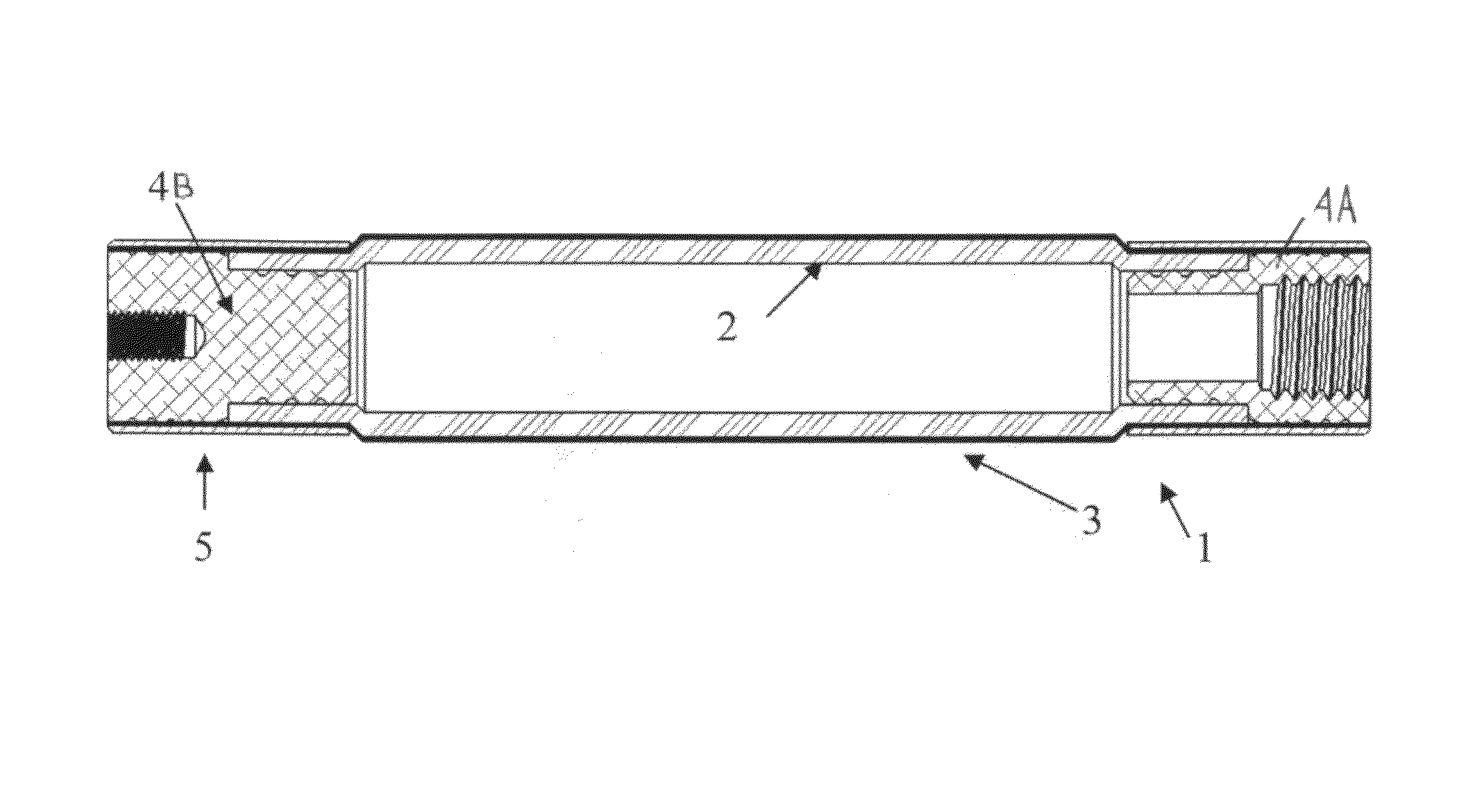
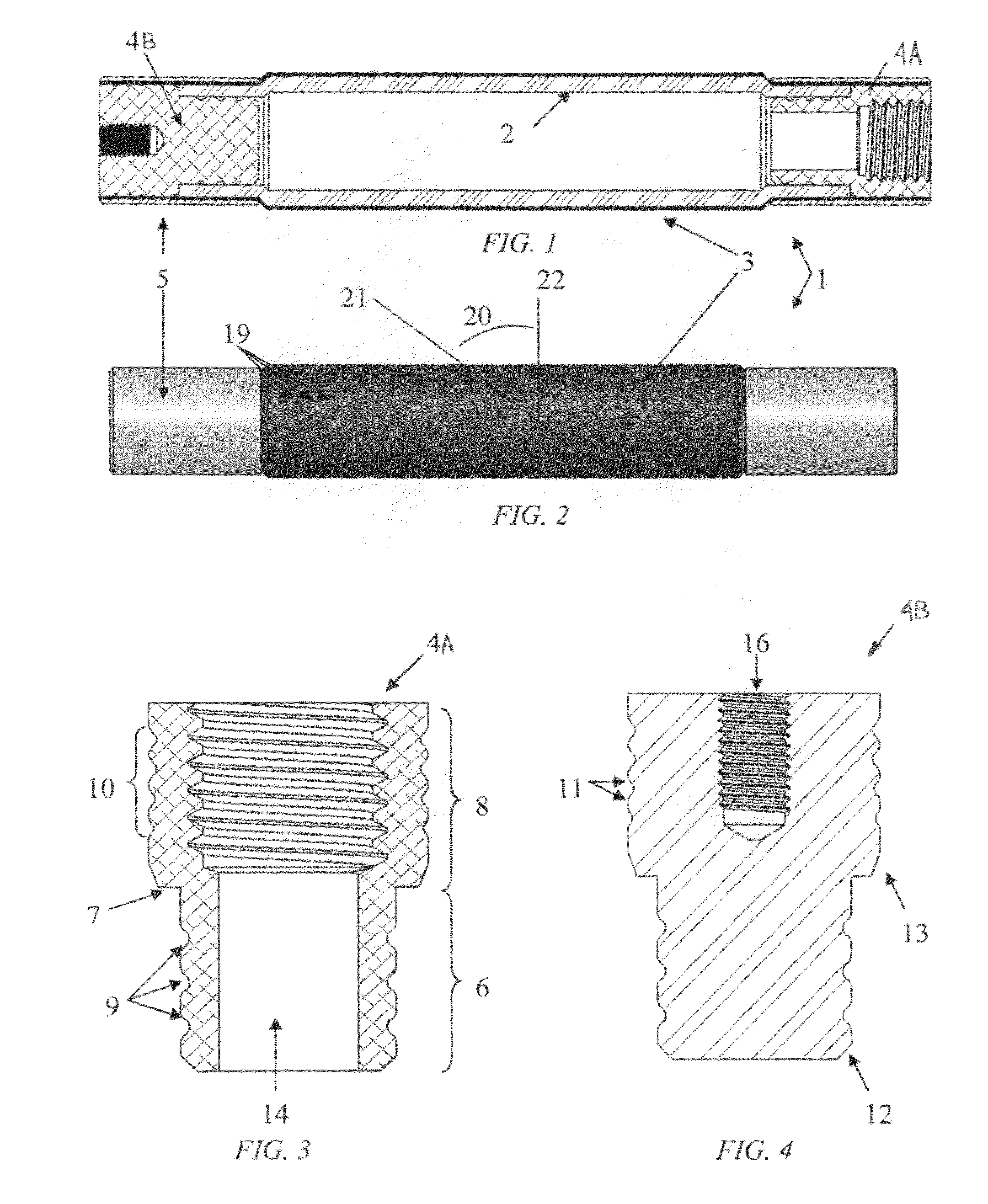
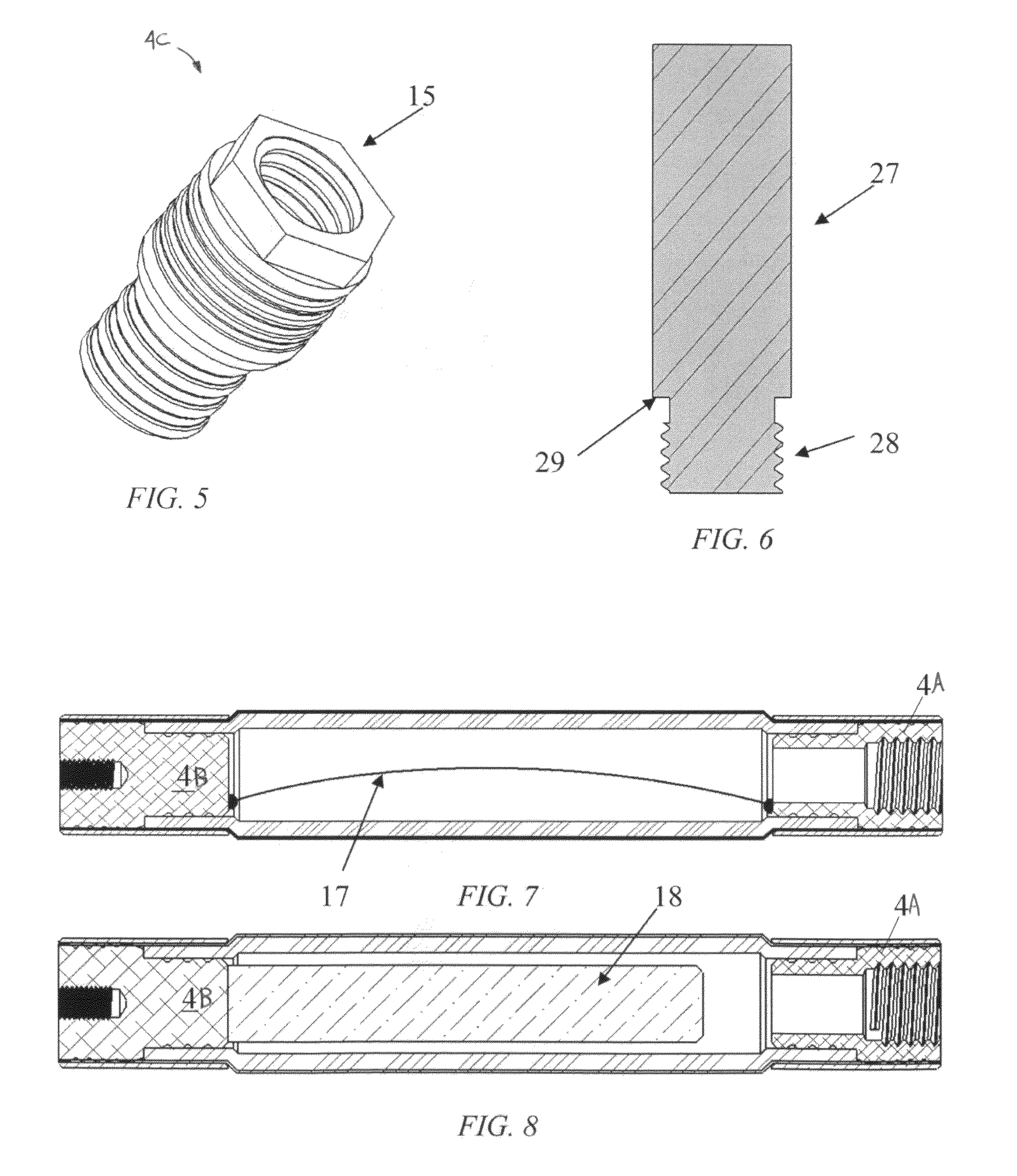
[0025]With combined reference to FIGS. 1 and 2, the actuator 1 comprises an inner elastic fluid bladder 2 surrounded by a stiff braided sleeve 3. End fittings 4 are attached to each end to seal the bladder 2 and allow for connection of the actuator 1 to other component(s). A swage tube 5 is fitted around a set of end fittings 4 (shown here as two different end fittings 4A, 4B), sandwiching the braided sleeve 3 and bladder 2 as shown. The swage tube 5 has a constant wall-thickness and constant-diameter, and upon fitting is plastically deformed to provide a fluid seal and a strong mechanical connection.

[0026]The end fittings 4A, 4B are preferably constructed from a lightweight but strong material such as, but not limited to, aluminum, titanium, plastic, or fiber reinforced polymer. These can be machined, molded, or manufactured in any other way which allows for the necessary features ...


PUM

PropertyMeasurementUnit
internal volumeaaaaaaaaaa
diameteraaaaaaaaaa
mechanical workaaaaaaaaaa

Abstract

A fluidic artificial muscle actuator consisting of an inner elastic bladder surrounded by a braided filament sleeve and sealed off on either end with end fittings. Pressurization of the actuator produces force and / or motion through radial movement of the bladder and sleeve which forces the sleeve to move axially. Both contractile and extensile motions are possible depending on the geometry of the braided sleeve. The fluidic artificial muscle actuator is manufactured using a swaging process which plastically deforms swage tubes around the end fittings, braided sleeve, and pressure bladder, creating a strong mechanical clamping action that may be augmented with adhesive bonding of the components. The swaging system includes the swaging die and associated components which are used to plastically deform the swage tube during assembly of the actuator.

Description

CROSS-REFERENCE TO RELATED APPLICATION(S)[0001]The present application is a continuation-in-part of U.S. application Ser. No. 11 / 502,360 filed Aug. 11, 2006, now U.S Pat. No. 7,837,144 and further derives priority from U.S. provisional application Ser. No. 61 / 131,719 filed 11 Jun. 2008.BACKGROUND OF THE INVENTION[0002]1. Field of the Invention[0003]The present invention generally relates to actuators used for performing mechanical work and, more particularly, to fluidic artificial muscles, artificial muscle actuators, or McKibben artificial muscles.[0004]2. Description of Prior Art[0005]Fluidic artificial muscles (also known as artificial muscle actuators, or McKibben artificial muscles, among other names), are simple mechanical actuators that harness pressurized fluid (air, water, oil, etc.) to generate significant forces and deflections.[0006]Fluidic artificial muscles commonly comprise an inner elastic fluid bladder surrounded by a stiff braided sleeve that is sealed on each end ...

Claims


Application Information

Patent Timeline
Patent Type & Authority Patents(United States)
IPC IPC(8): F01B19/04
CPCB63B1/248B63G8/18B63H25/382B23P11/005B21D39/04Y10T29/53717Y10T29/494Y10T29/5367
Inventor WOODS, BENJAMIN K. S.KOTHERA, CURTWERELEY, NORMAN M.
Owner INNOVITAL LLC
Why Eureka
Try Eureka