Conveyor device for transporation structures

a technology for conveying structures and transportation structures, which is applied in the direction of mechanical conveyors, conveyor parts, roller-ways, etc., can solve problems such as bulky system construction, and achieve the effect of facilitating the fitting of drive modules and increasing the flexibility of the system

Inactive Publication Date: 2018-11-13
EISENMANN SE
View PDF16 Cites 3 Cited by
  • Summary
  • Abstract
  • Description
  • Claims
  • Application Information

AI Technical Summary

Benefits of technology

[0013]According to the invention, the drive installation is not fixedly installed on the path unit, but may also be fitted during active operation, or in the case of an installed conveyor device be refitted or retrofitted in order to extend the existing conveyor device, respectively. Moreover, the conveyor device may be transported in a more space-saving manner, since the drive installations in particular typically protrude significantly from the longitudinal profiled sections of the conveyor device, rendering the system bulky.
[0014]It is particularly favorable for the drive module to comprise a drive unit which has a motor and a drive wheel, drivable by said motor, and which is releasably attachable and fixable to the drive fastening installation. The flexibility of the system is increased in this way, on the one hand. Since the drive unit in practice determines the weight of the drive module, fitting of the drive module is facilitated, on the other hand. In this case, only the drive fastening installation without the drive unit may initially be fastened to the longitudinal profiled section, the drive unit being subsequently attached to the drive fastening installation.
[0019]It is moreover advantageous for one jaw of the drive fastening installation to be a drive clamping jaw and to be a first part of a pivoting hinge which comprises an additional pivoting jaw as a second part which is pressed toward the first part of the pivoting hinge by means of a pre-tensioning unit. If and when the drive unit is supported by this pivoting jaw it is ensured that the drive unit, or the drive wheel thereof, respectively, is always pressed in the direction of the transportation structure, on account of which a reliable drive contact is guaranteed.
[0021]For simple fitting or dismantling of the drive unit it is particularly advantageous when at least one retaining unit is configured as a mushroom pin, and one receptacle that is conceived for this retaining unit is configured as a slot-type receptacle or a key-hole receptacle.

Problems solved by technology

Moreover, the conveyor device may be transported in a more space-saving manner, since the drive installations in particular typically protrude significantly from the longitudinal profiled sections of the conveyor device, rendering the system bulky.

Method used


Image

  • Conveyor device for transporation structures
  • Conveyor device for transporation structures
  • Conveyor device for transporation structures

Examples


Embodiment Construction

[0043]While this invention is susceptible of embodiment in many different forms, there is shown in the drawings and will herein be described in detail one or more embodiments with the understanding that the present disclosure is to be considered as an exemplification of the principles of the invention and is not intended to limit the invention to the embodiments illustrated.

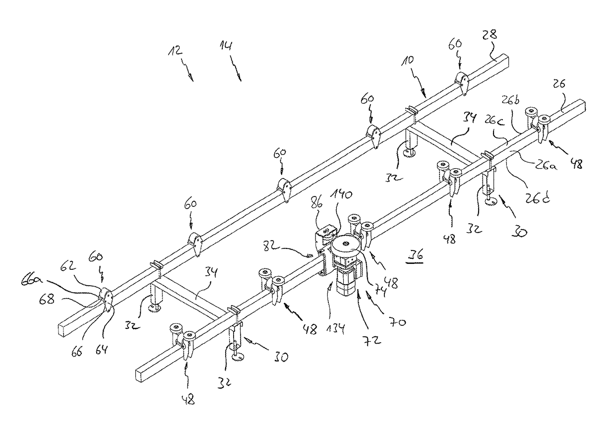
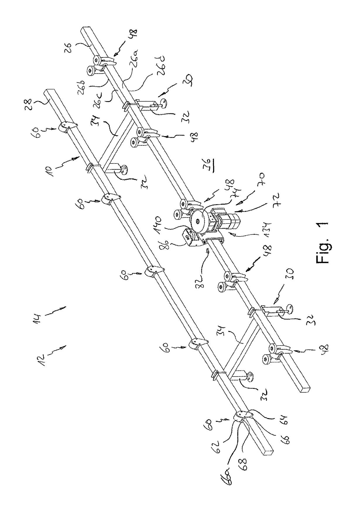
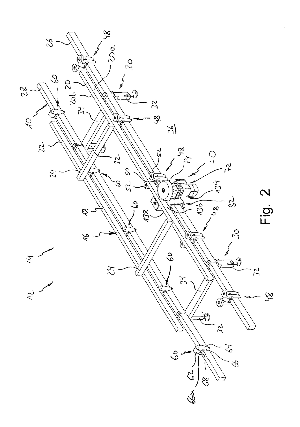
[0044]Reference is initially made to FIGS. 1 and 2 which each show a path unit 10 of modular construction of a conveyor device 12 which is conceived as a roller-track conveyor 14. The conveyor device 12 and consequently the roller-track conveyor 14 are constructed from a plurality of such path units 10. The conveyor device 12 thus defines a conveyor path which is formed from a plurality of sequentially disposed path units 10.

[0045]A transportation structure 16 for items to be conveyed is additionally shown running on the roller-track conveyor 14 in FIG. 2. Said transportation structure 16 in the present exemplary...


PUM


Abstract

A conveyor device for conveying transportation structures, particularly transportation skids in the automobile industry, having a conveyor path that is formed from a plurality of path units arranged one behind the other, each of the path units having two parallel longitudinal profiled sections. A drive system for said transportation structures is provided that has at least one drive device which, when said conveyor device is in operation, is arranged on at least one of said longitudinal profiled sections. The drive system includes at least one drive module which can be detachably secured to the longitudinal profiled section by means of a drive-securing device.

Description

RELATED APPLICATIONS[0001]This application is a national phase of International Patent Application No. PCT / EP2015 / 001587, filed Aug. 1, 2015, which claims the filing benefit of German Patent Application No. 10 2014 012 211.5, filed Aug. 16, 2014, the contents of both of which are incorporated herein by reference.FIELD OF THE INVENTION[0002]The invention relates to a conveyor device for conveying transportation structures, in particular transportation skids in the automotive industry, having[0003]a) a conveyor path that is formed from a plurality of sequentially disposed path units, each of said path units comprising two mutually parallel longitudinal profiled sections;[0004]b) a drive system for the transportation structures, having at least one drive installation which is disposed on at least one of the longitudinal profiled sections during operation of the conveyor device.BACKGROUND OF THE INVENTION[0005]Conveyor devices of this type are employed in the form of roller-track convey...

Claims


Application Information

Patent Timeline
Patent Type & Authority Patents(United States)
IPC IPC(8): B65G13/06B65G13/071B65G39/18B65G35/06
CPCB65G13/071B65G39/18B65G35/06B65G35/00B65G2201/0294
Inventor ROBBIN, JOERG
Owner EISENMANN SE
Why Eureka
Try Eureka