
Method of implementing dynamic channel allocation in a cellular radio system

Inactive Publication Date: 2002-08-13
WSOU INVESTMENTS LLC
View PDF26 Cites 27 Cited by
  • Summary
  • Abstract
  • Description
  • Claims
  • Application Information

AI Technical Summary

Benefits of technology

The method of the invention provides distinct advantages compared with the prior art. The invention enables dynamic channel allocation to be performed in a cellular radio system. This improves the flexibility of the system in connection with different traffic loads and enhances the utilization of the frequency spectrum. Also the need for frequency planning is substantially reduced. The method of the invention thus enables a reuse of traffic channels in different subcells within a cell. The advantages of dynamic channel allocation are particularly emphasised in networks with small cell sizes.

Problems solved by technology

The requirement that in the current GSM system a BCCH carrier frequency is to be transmitted uninterruptedly at a constant power level prevents the use of certain methods developed to improve connection quality and system capacity on control and traffic channels of a BCCH carrier frequency.
A disadvantage in fixed channel allocation is that precise and laborious frequency planning is required to allow co-channel interference to be minimised.
In addition, fixed channel allocation adjusts poorly to variations in traffic loads.
The above disadvantages in fixed channel allocation are emphasised in cellular radio systems with a small cell size, such as office systems, where variations in radio traffic load are usually larger than in macrocell systems, which complicates radio network planning.

Method used


Image

  • Method of implementing dynamic channel allocation in a cellular radio system
  • Method of implementing dynamic channel allocation in a cellular radio system
  • Method of implementing dynamic channel allocation in a cellular radio system

Examples


Embodiment Construction

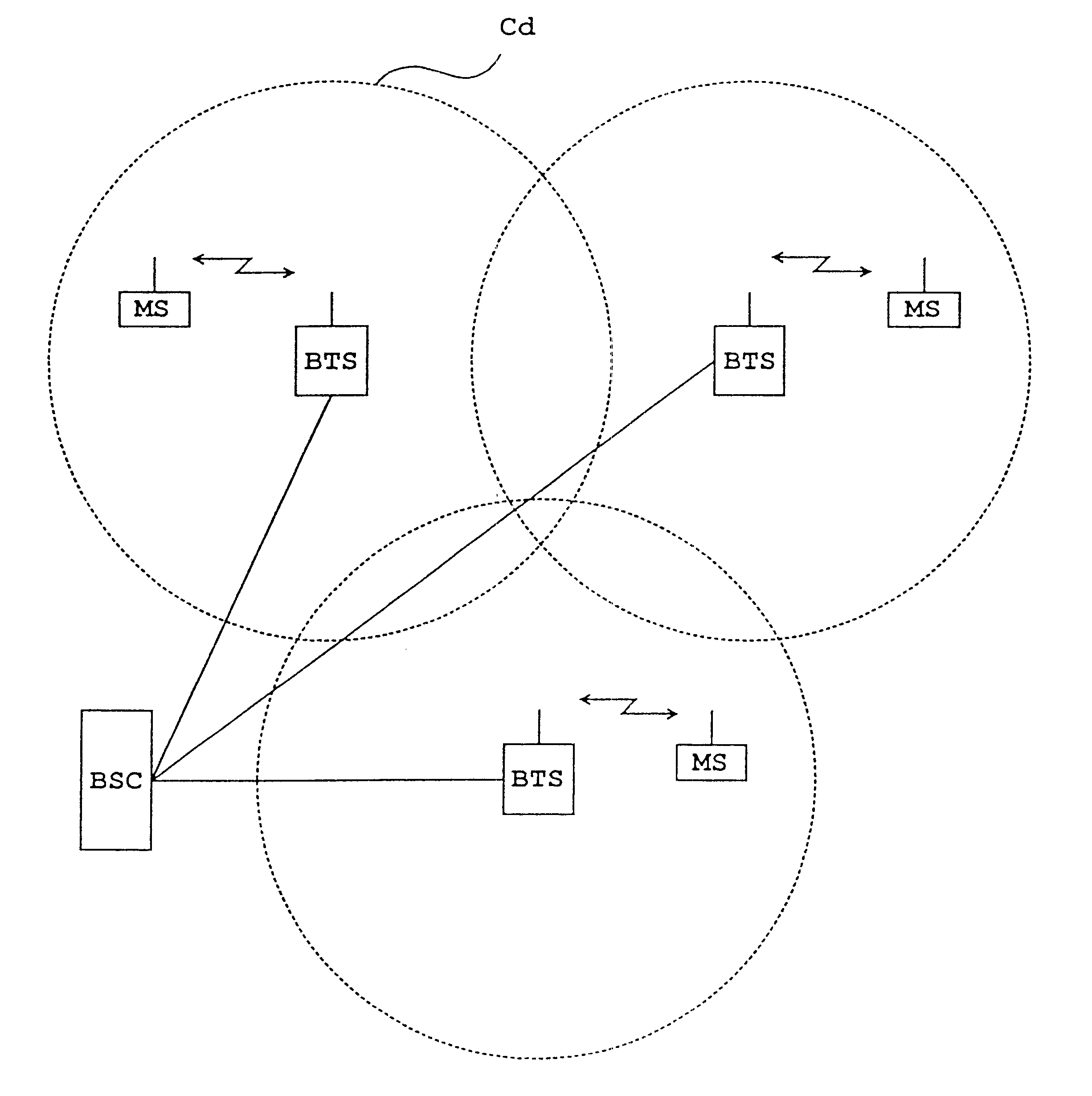
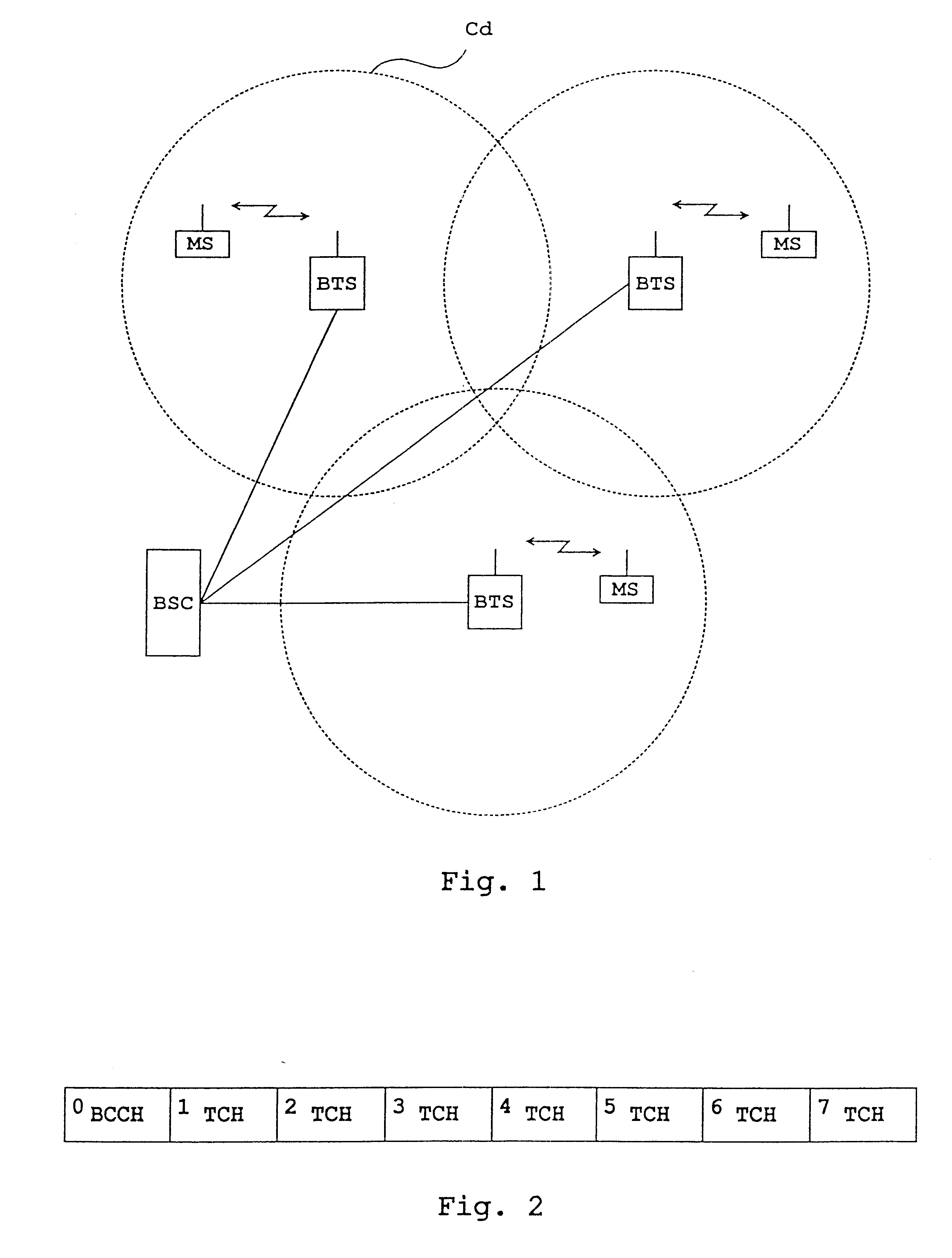
FIG. 1 illustrates a cellular radio system, to which a method of the invention can be applied. A cell Cd represents a cell applying dynamic channel allocation. In a cellular radio system, each cell has at least one base station BTS, which communicates with subscriber terminals MS located within its area. A base station controller BSC, in turn, controls the operation of one or more base stations BTS. In cellular radio systems, a user's speech and data traffic between a base station and a subscriber terminal is transmitted on traffic channels. Between a base station and a subscriber terminal are also needed various control messages and system information, which are transmitted on control channels. The method of the invention can be applied to any cellular radio system utilizing an FDMA multiple access system or a time-division multiple access system TDMA. Although in the following description the method of the invention is applied to the GSM system, it is not restricted to the system....


PUM


Abstract

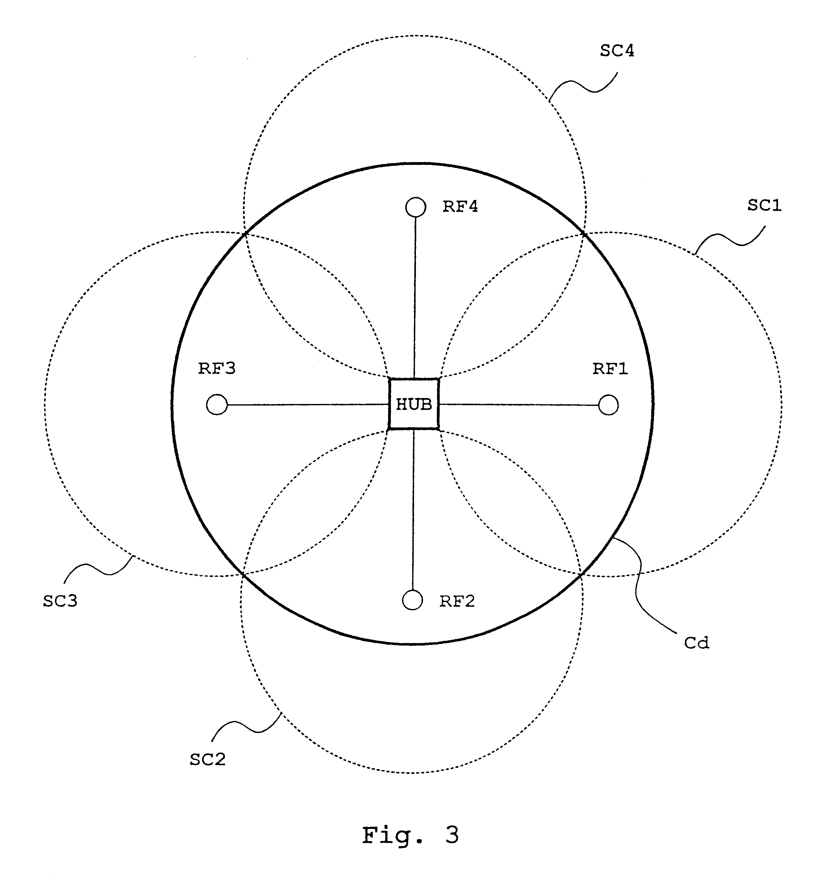
A method of implementing dynamic channel allocation in a cellular radio system. The cellular radio system includes, in each cell, at least one base station communicating with subscriber terminals within its area. The system includes, in one cell, at least two subeeils, which include an anrenna unit and in which all available frequencies are dynamically used. All antenna units listen to control channels that subscriber terminals use for connection set-up and a base station measures the power level of the control channels through the antenna units, on the basis of which an antenna unit providing the strongest sigxzal is selected for conricction set-up. The base station measures through the antenna units the interference level of all available traffic channels, on the basis of which that traffic channel in an antenna unit selected for connection set-up which has the least interference is selected for communication. The base station measures through the antenna units the power level of the signals of subscriber terminals having a uaffic connection.

Description

1. Field of the InventionThe invention relates to a method of implementing dynamic channel allocation in a cellular radio system, the system comprising: in each cell, at least one base station which communicates with subscriber terminals located within its area, which broadcasts at least at one carrier frequency and which transmits information about itself on control channels to subscriber terminals; in at least one cell, at least two subcells which comprise an antenna unit and in which all available frequencies are dynamically used; and a base station of the system measuring, through each antenna unit, a level of interference of all available traffic channels, on the basis of which that traffic channel in an antenna unit selected for connection set-up which has the least interference is selected for communication.2. Description of the Related ArtIn cellular radio systems, a user's speech and data between a base station and a subscriber terminal are transmitted on a traffic channel....

Claims


Application Information

Patent Timeline
IPC IPC(8): H04Q7/36H04Q7/38H04W16/10H04W16/12
CPCH04W16/10H04W16/12H04W24/10H04W28/04H04W48/08H04W72/04
Inventor POSTI, HARRI
Owner WSOU INVESTMENTS LLC
Learn More