Methods, apparatus and products for production of fluids from subterranean formations

a technology of subterranean formations and fluid extraction, applied in the direction of drilling pipes, drilling casings, borehole/well accessories, etc., can solve the problems of incurred expenses, cost, loss of revenue,

Inactive Publication Date: 2018-11-13
WAID MARGARET COWSAR +1
View PDF5 Cites 1 Cited by
  • Summary
  • Abstract
  • Description
  • Claims
  • Application Information

AI Technical Summary

Problems solved by technology

This can become an expensive problem, because not only is there loss in revenue because the produced fluid contains less hydrocarbon, there are incurred expenses by the extra cost of transporting the oil / filtrate and the cost of separating the mud filtrate from the oil.
Additional costs may occur because almost all mud filtrate, whether it is oil based or is water based contains significant amounts of water (as water sources are drilled through), and water together with water velocity causes corrosion in pipelines.
Indeed, water may significantly fill a pipeline over time, reducing the amount of hydrocarbons which may be transported.
Deep-reading resistivity logs designed to see beyond the invaded zone, a few feet from the borehole, often did not see deep enough, and these needed correction to obtain true formation resistivity.
OTC 18201, Advances in Fluid Sampling With Formation Testers for Offshore Exploration, C. Del Campo et al., Offshore Technology Conference, May 1-4, 2006, discloses that formation fluid samples provide valuable information for field development, and that drilling mud filtrate contamination reduces the sample quality drastically, and the current industry technique to obtain clean fluid samples requires a long pumping time.
This can be costly, especially in deep offshore wells.
With this mudcake model there are higher rates of invasion soon after drilling.
Prior art solutions suggest reducing the flow rate but in wells drilled with OBM an unacceptably long clean-up time would result.
The Pinda formation in Block 2 offshore Angola presents just such a challenge.
Interpretation of transient focused-sampling measurements acquired in wells drilled with oil-based mud (OBM) is particularly challenging.

Method used


Image

  • Methods, apparatus and products for production of fluids from subterranean formations
  • Methods, apparatus and products for production of fluids from subterranean formations
  • Methods, apparatus and products for production of fluids from subterranean formations

Examples


examples

[0071]The following example is merely provided to illustrate one non-limiting embodiment of the present invention.

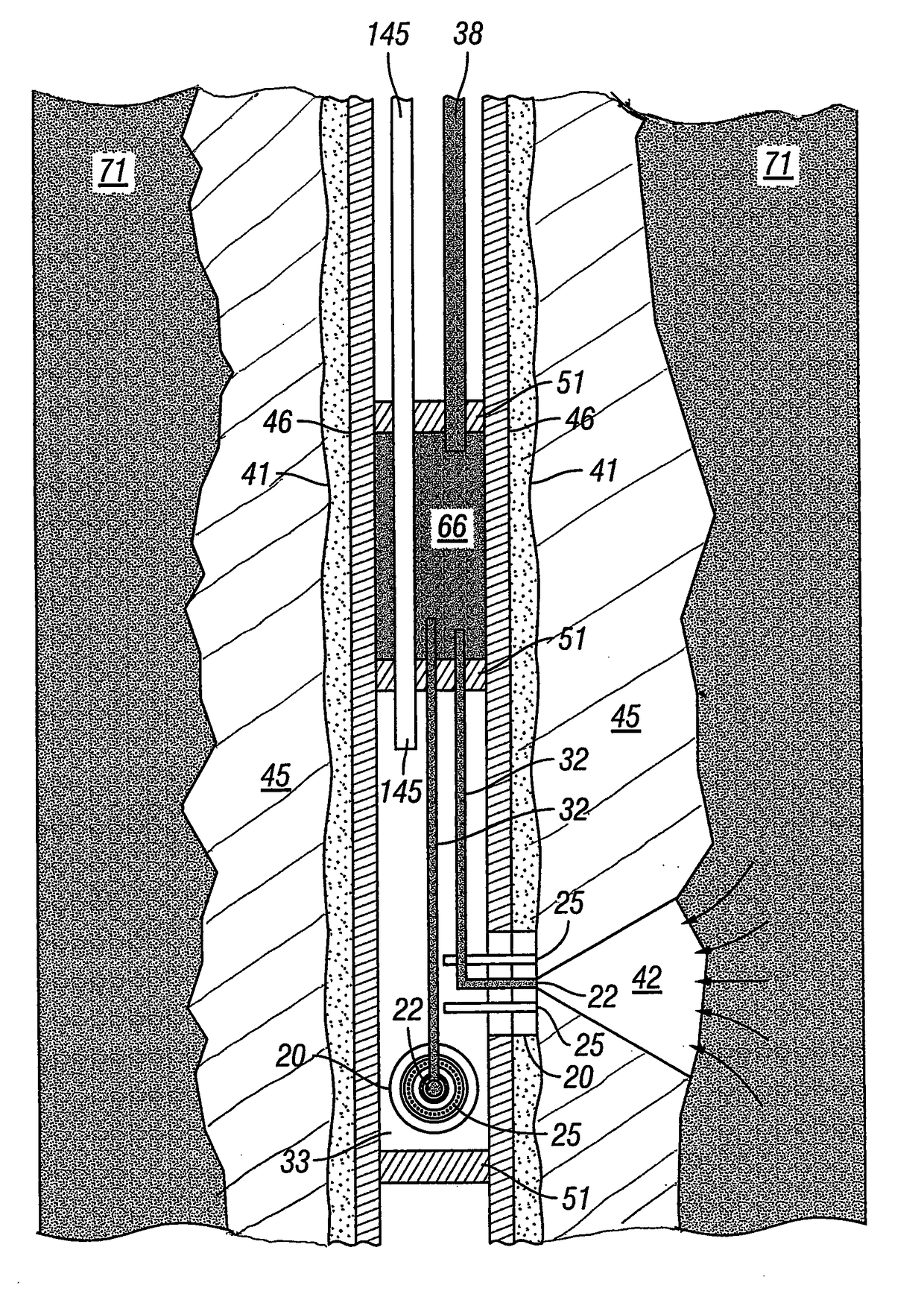
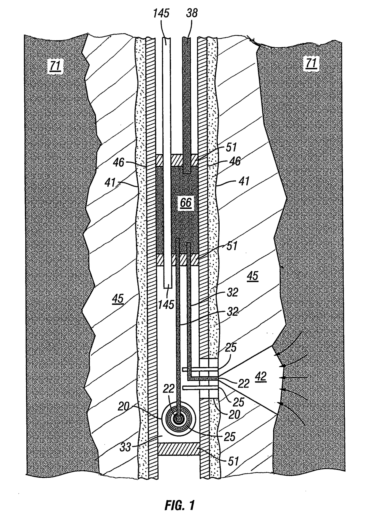
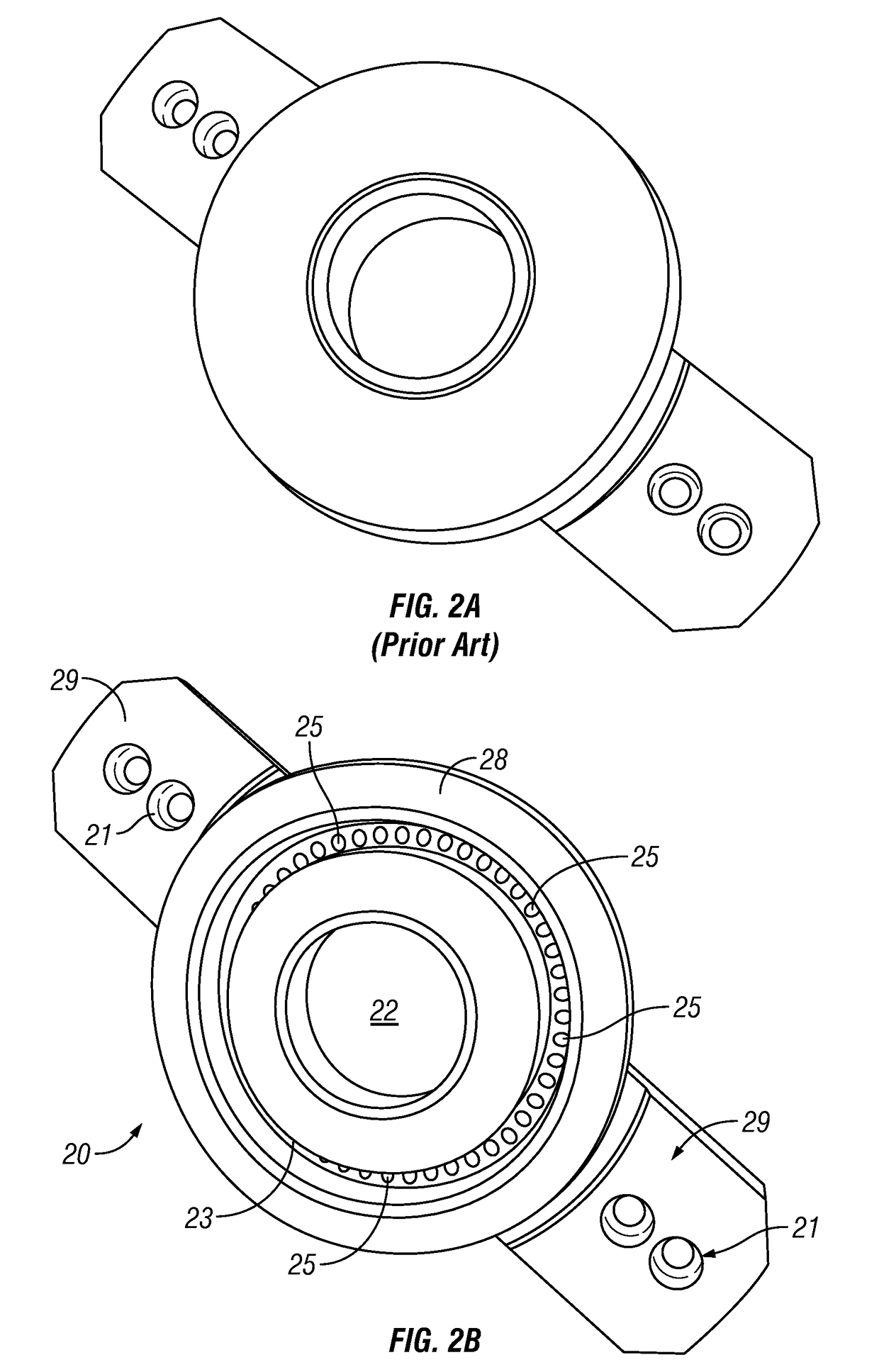
[0072]As a prophetic example—an Austin Chalk well just above a certain Shale play somewhere in Texas is producing over 1000 barrels a day. At $100 per barrel, that amounts to over $100,000 per day or over $36,500,000 per year, that is, if the production were pure oil. Unfortunately, the production averages at least 10% mud filtrate, and this will continue for years. With the production averaging 10% mud filtrate, the annual income is reduced by $3,650,000 per year. Of course this loss of income is further exacerbated by the extra cost of transporting the oil / filtrate and the cost of separating the mud filtrate from the oil. The methods, apparatus and products of the present invention provide for the separation of oil and filtrate down hole and each is produced via separate tubing. Now the production is pure (or relatively pure) hydrocarbon, the extra oil transportation c...


PUM


Abstract

Methods, apparatus and products for separating oil and mud filtrate down hole and production of each to the surface via separate tubing, that includes custom engineered drill pipe for which two types of openings called ports have been cut or drilled: production ports and isolation ports. The production port produces formation fluid (normally hydrocarbons) from a perforation. In one non-limiting embodiment, a tube is welded to the inside of the casing at each production port to transmit the formation fluid to the top of the drill pipe section where it is attached to a custom engineered casing collar (described below) designed to allow flow to the next drill pipe section of the device. The isolation port produces mud filtrate from the adjacent borehole wall exterior to the casing, and these isolation ports are arranged in a pattern around each production port to keep mud filtrate in the invaded zone from reaching the production port. The number and placement of the production ports as well as the number, placement and shape of the isolation ports are determined using the information regarding the perforating design and other information such as the filtrate type and estimates of invasion depth as determined by well logs. Packers are set above and below the apparatus to provide an “isolation” chamber to contain the produced filtrate. Tubing through the upper packer will produce the filtrate to the surface via differential pressure or pumping. After the casing has been cemented, the perforating guns in the production ports are fired to begin production of formation fluid.

Description

RELATED APPLICATION DATA[0001]This patent application claims priority from U.S. Provisional Patent Application Ser. No. 61 / 987,374 filed May 1, 2014 and from U.S. Patent Application Ser. No. 62 / 010,346 filed Jun. 10, 2014, the applications of which are herein incorporated by reference.BACKGROUND OF THE INVENTION[0002]1. Field of the Invention[0003]The present invention relates to the extraction of fluids from subterranean formations. In another aspect, the present invention relates to the extraction of fluids from subterranean formations drilled by mud rotary drilled wells. In even another aspect, the present invention relates to the extraction of fluids from mud drilled hydrocarbon wells, water supply wells, and monitoring wells. In still another aspect, the present invention relates to the extraction of a target fluid and mud filtrate down hole and with each of the target fluid and the mud filtrate being produced to the surface via separate tubing. In yet another aspect, the prese...

Claims


Application Information

Patent Timeline
Patent Type & Authority Patents(United States)
IPC IPC(8): E21B43/14E21B43/38E21B17/18E21B43/12E21B47/06E21B43/114E21B49/08
CPCE21B43/38E21B17/18E21B43/114E21B49/088E21B47/06E21B49/087E21B43/121E21B43/14
Inventor WAID, MARGARET COWSARWAID, CHARLES CARTER
Owner WAID MARGARET COWSAR
Why Eureka
Try Eureka