Circumferential electrode array for tissue ablation

a tissue ablation and circumferential electrode technology, applied in medical science, surgery, diagnostics, etc., can solve the problems of inability to surgically remove or resected tumors, and inability to achieve tumor removal. , to achieve the effect of improving the heating of large tumor areas, uniform temperature gradient, and reducing the loss of electrode effectiveness

Active Publication Date: 2018-11-20
WISCONSIN ALUMNI RES FOUND
View PDF18 Cites 0 Cited by
  • Summary
  • Abstract
  • Description
  • Claims
  • Application Information

AI Technical Summary

Benefits of technology

[0010]The present invention provides improved heating of large tumor areas by encircling the tumor with electrodes placed just outside the tumor margin. By heating the tumor “outside in” rather than “inside out” by center placed electrodes, a more uniform temperature gradient can be obtained without excessive electrode temperatures which can lead to loss of electrode effectiveness. Placement of the electrodes outside the tumor creates less risk of tumor seeding, i.e., the spreading cancer cells by the piercing of the tumor tissue with the electrodes. The switching among electrodes prevents shielding effects between the electrodes producing uneven tissue heating. In particular, a “round robin” energizing of opposed electrodes allows the energy to be directed through the center of the tumor.
[0011]While the inventors do not wish to be bound by a particular theory, it is believed that increased and early peripheral heading provided by the invention causes a restriction of blood flow to the tumor reducing heat loss through vessels and further promoting tumor cell destruction.
[0012]Specifically, then, the present invention provides an electrode array for radiofrequency ablation of a tumor where the array includes a set of elongate electrodes for insertion through tissue of an organ and a holder positioning the electrodes in proximity to each other within a volume of tissue to be ablated. A radiofrequency power supply independently applies electricity to the electrodes in a pattern avoiding simultaneous activation of adjacent electrodes with the same polarity of radiofrequency power to prevent electrostatic shielding effects that reduce the heating between adjacent electrodes having the same polarity of radiofrequency power.

Problems solved by technology

Malignant liver tumors are a substantial problem in the United States and worldwide.
Nevertheless, surgical resection or removal of the tumors is not always possible.
Resection of multiple, deep lesions may require the loss of an unacceptable amount of hepatic parenchyma.
Extensive hepatic resections increase post-operative morbidity and mortality, including post-operative hepatic failure.
In addition, the need for transfusion during hepatic resection increases the tumor recurrence rate, probably due to poorly understood immunological mechanisms.
In cases where surgery is not practical, RF ablation for tumor destruction may be preferred, yet it can be difficult to ablate large tumors reliably, especially in perivascular tissue and at tumor margins.
It is difficult to provide uniformly high temperatures throughout a large tumor volume, particularly near blood vessels, which provide a heat sink, and near the edges of the tumor, leading to a substantial risk of incomplete treatment of the tumor.

Method used


Image

  • Circumferential electrode array for tissue ablation
  • Circumferential electrode array for tissue ablation
  • Circumferential electrode array for tissue ablation

Examples


Embodiment Construction

I. Partitioning Electrode Array

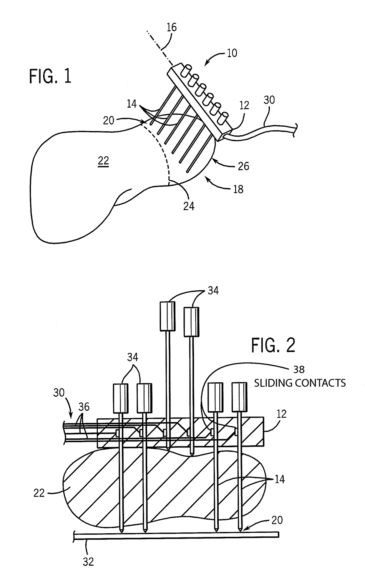
[0059]Referring now to FIG. 1, an electrode array assembly 10 of a first embodiment of the present invention includes a holder 12 supporting a number of elongate electrodes 14 spaced along an axis 16 to define a generally planar surface 18 among them. The surface 18, for example, may be 8 cm long and 10 cm wide.

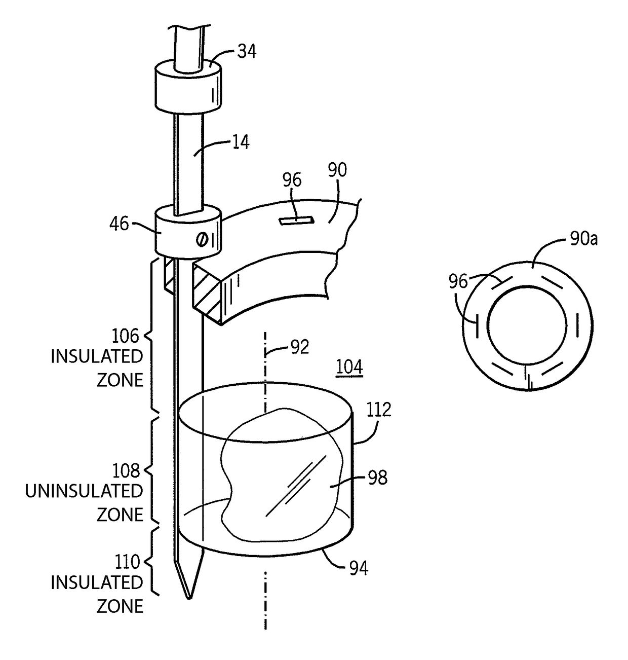
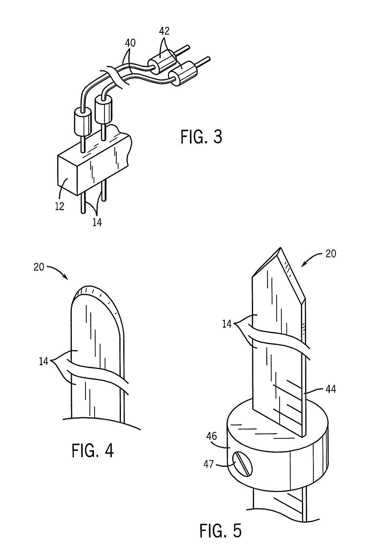
[0060]Sharpened tips 20 of the elongate electrodes 14 may be inserted into the liver 22 at an insertion line 24 to isolate one lobe 26 of the liver 22 for resection. The elongate electrodes 14 may, for example, be constructed of a biocompatible stainless steel.

[0061]The holder 12 may be, for example, an insulating plastic block having holes cut in the holder 12 to receive metallic shafts of the elongate electrodes 14 at regular intervals. In a preferred embodiment, the separation of the electrodes is approximately 1.5 cm. The elongate electrodes 14 may be fixed to the holder 12 so as to be moved in unison for rapid insertion. Each elongate elect...


PUM


Abstract

An electrode array supports multiple electrodes and energizes them so that adjacent electrodes do not have the same polarity. In one embodiment, the electrodes are held about a circumference outside and surrounding a tumor and opposed electrodes are energized in a round robin fashion to promote current flow through the center of the tumor from a variety of angles.

Description

CROSS-REFERENCE TO RELATED APPLICATIONS[0001]This application is a continuation-in-part of U.S. application Ser. No. 10 / 945,380 filed Sep. 20, 2004 and entitled: “Electrode Array for Tissue Ablation”, hereby incorporated by reference. This application claims the benefit of U.S. provisional application 60 / 946,657 filed Jun. 27, 2007, hereby incorporated by reference.STATEMENT REGARDING FEDERALLY SPONSORED RESEARCH OR DEVELOPMENT[0002]This invention was made with United States Government Support awarded by the following agency:[0003]NIH DK058839, HL56143.[0004]The United States government has certain rights in this invention.BACKGROUND OF THE INVENTION[0005]The present invention relates to radiofrequency (RF) ablation of tumors and, in particular, to an apparatus and method for safely ablating large tumors, for example, within organs such as the liver.[0006]Malignant liver tumors are a substantial problem in the United States and worldwide. Virtually all patients who succumb to colore...

Claims


Application Information

Patent Timeline
Patent Type & Authority Patents(United States)
IPC IPC(8): A61B18/18A61B18/14A61B17/00A61B18/00A61B18/12
CPCA61B18/1477A61B2560/0418A61B2017/00022A61B2017/00026A61B2018/0075A61B2018/00654A61B2018/00726A61B2018/00755A61B2018/00791A61B2018/00797A61B2018/00827A61B2018/00875A61B2018/124A61B2018/143A61B2018/1432A61B2018/1467A61B2017/00017
Inventor WEBSTER, JOHN G.HAEMMERICH, DIETERWILL, JAMES ARTHURMAHVI, DAVIDO'ROURKE, ANNSCHUTT, DAVID JAMES
Owner WISCONSIN ALUMNI RES FOUND
Why Eureka
Try Eureka