
Hall effect thruster and a space vehicle including such a thruster

a technology of hall effect and thruster, which is applied in the direction of machines/engines, cosmonautic vehicles, transportation and packaging, etc., can solve the problem of occupying a large amount of the inside space of a space vehicle including such a thruster, and achieve the effect of occupying less spa

Active Publication Date: 2018-11-20
SAFRAN SPACECRAFT PROPULSION
View PDF5 Cites 0 Cited by
  • Summary
  • Abstract
  • Description
  • Claims
  • Application Information

AI Technical Summary

Benefits of technology

The technical effect of this patent is to create a Hall effect thruster that takes up less space in the space vehicle it is placed in.

Problems solved by technology

In particular, because of that nozzle, a particularly large amount of the inside space of a space vehicle including such a thruster is already occupied.

Method used


Image

  • Hall effect thruster and a space vehicle including such a thruster
  • Hall effect thruster and a space vehicle including such a thruster
  • Hall effect thruster and a space vehicle including such a thruster

Examples


Embodiment Construction

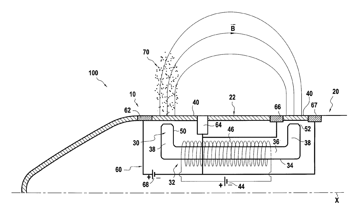
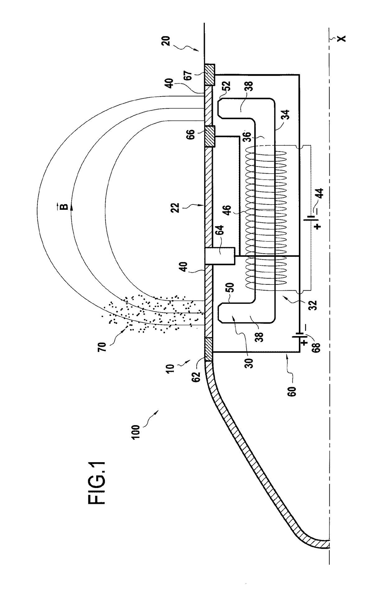
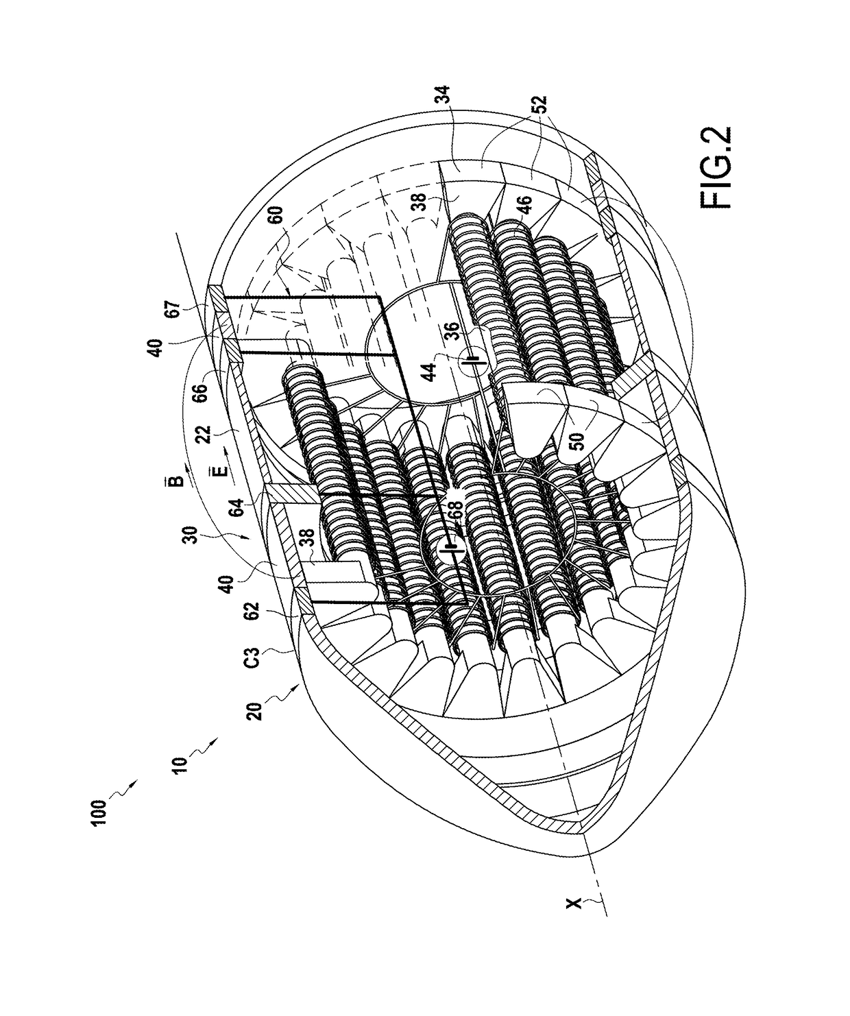
[0035]FIGS. 1 and 2 show a space vehicle 100, specifically a satellite, including a Hall effect thruster 10 of the invention.

[0036]The satellite is a satellite that is to orbit in the earth's atmosphere and remain at an altitude in the range 100 kilometers (km) to 300 km.

[0037]Advantageously, this altitude is relatively low, which enables certain pieces of equipment (communications equipment, cameras, etc.) to be of a size and thus of a mass that are relatively small. Conversely, at this altitude, the earth's atmosphere opposes resistance to the passage of the satellite that is low but not zero. It is therefore necessary to compensate for the resulting drag.

[0038]The function of the thruster 10 is to supply the satellite with thrust, enabling it to be maintained in operation at the desired altitude.

[0039]It also serves to make orbital changes or corrections.

[0040]Advantageously, a thruster of the invention, such as the thruster 10, when coupled to electric energy power supply means ...


PUM


Abstract

A Hall effect thruster arranged inside a wall and including a magnetic circuit and an electric circuit including an anode, a first cathode, and a voltage source. The magnetic circuit and the electric circuit are arranged in such a manner as to generate magnetic and electric fields around the wall. In every meridian section, the magnetic circuit presents an upstream magnetic pole and a downstream magnetic pole arranged at the surface of the wall and spaced apart from each other; and the anode and the first cathode are situated on either side of the upstream magnetic pole.

Description

FIELD OF THE INVENTION[0001]The present invention relates to the field of air-breathing Hall effect thrusters.TECHNOLOGICAL BACKGROUND[0002]Usually, an air-breathing Hall effect thruster comprises:[0003]a nozzle for collecting, accelerating, and ejecting particles by the thruster when it is in operation;[0004]an electric circuit comprising an anode, a cathode downstream from the anode, and a voltage source for emitting electrons via the cathode and attracting electrons via the anode; and[0005]a magnetic circuit for generating a magnetic field in the nozzle axially downstream from the anode, the magnetic field being directed in a direction that is substantially radial relative to the thrust axis.[0006]By way of example, such a thruster is described in Document US 2003 / 0046921.[0007]In practice, the nozzle is generally annular in shape to enable the magnetic circuit to generate a radial magnetic field. The nozzle thus comprises both an inside wall and an outside wall; the particles pa...

Claims


Application Information

Patent Timeline
Patent Type & Authority Patents(United States)
IPC IPC(8): F03H1/00B64G1/40H05H1/54
CPCB64G1/405F03H1/0006F03H1/0068H05H1/54F03H1/0062F03H1/0012B64G1/413
Inventor MARCHANDISE, FREDERIC RAPHAEL JEANVIAL, VANESSAZURBACH, STEPHAN
Owner SAFRAN SPACECRAFT PROPULSION
Learn More