Cavitation limiting strategies for pumping system

a technology of cavitation limitation and pumping system, which is applied in the direction of positive displacement liquid engine, instrument, borehole/well accessories, etc., can solve the problems of common operation under relatively harsh conditions, subject internal components to fairly extreme pressure, and the physics behind cavitation

Active Publication Date: 2018-11-20
CATERPILLAR INC
View PDF15 Cites 126 Cited by
  • Summary
  • Abstract
  • Description
  • Claims
  • Application Information

AI Technical Summary

Problems solved by technology

Such pumps commonly operate under relatively harsh conditions, often reciprocating at high speeds and subjecting internal components to fairly extreme pressures.
While the results of cavitation in the nature of erosion, pitting, cracking or other damage to pump components are readily recognized, the physics behind cavitation and the circumstances that can lead to cavitation have long defied attempts at a deeper understanding.

Method used


Image

  • Cavitation limiting strategies for pumping system
  • Cavitation limiting strategies for pumping system
  • Cavitation limiting strategies for pumping system

Examples


Embodiment Construction

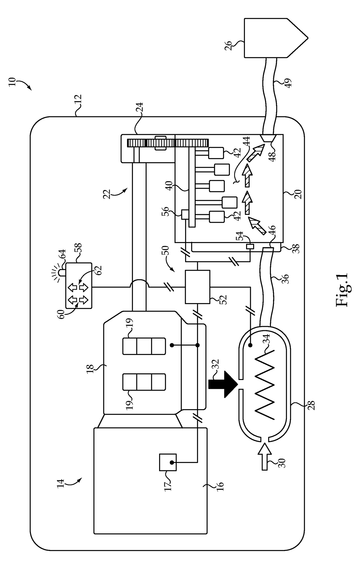
[0015]Referring to FIG. 1, there is shown a pumping system 10 according to one embodiment, and illustrated in the context of a fracking rig or the like having a frame 12 supporting a number of pumping system components. The frame 12 could include the bed of a mobile vehicle such as a truck or a towed trailer in certain embodiments, or could be a stationary structure. In still other instances, various components of the pumping system 10 might not be commonly supported at all. The pumping system 10 includes a power supply 14 having an engine 16, such as a conventional diesel internal combustion engine, coupled with a transmission 18 having a plurality of transmission gears 19. A driveline 22 couples the transmission 18 with a gearbox 24 coupled with and structured to drive a pump 20. In the illustrated embodiment, the pump 20 includes a reciprocating pump having a plurality of pumping elements such as plungers 42, each movable in suction or intake strokes and pumping strokes to transi...


PUM


Abstract

Operating a pumping system includes moving a pumping element to transition liquid through the pump, and determining a value based at least in part upon inlet pressure and pumping speed that is indicative of a pressure of the liquid within a bore susceptible to cavitation. Pumping speed and / or inlet pressure can be varied responsive to the determined value to limit cavitation.

Description

TECHNICAL FIELD[0001]The present disclosure relates generally to limiting cavitation in a pumping system, and relates more particularly to limiting cavitation by varying pumping speed or inlet pressure based on an indirect determination of a liquid pressure within the pump.BACKGROUND[0002]Pumps are used in all manner of commercial, industrial, and household applications, from small pumping mechanisms in household appliances up to large scale industrial and resource extraction systems, for example. While there are nearly as many different types of pump designs as there are pump applications, two common pump types are reciprocating pumps and rotary pumps. In a rotary pump, an impeller is commonly provided to suck liquid into the pump housing and discharge it at a pump outlet for whatever the end use might be. Reciprocating pumps generally include one or more plungers that travel in a linear manner, alternating between an intake stroke and a pumping stroke. Other known pumps include di...

Claims


Application Information

Patent Timeline
Patent Type & Authority Patents(United States)
IPC IPC(8): F04B11/00F04B49/10F04B17/05E21B43/267G08B21/18F04B53/22F04B53/16F04B53/14F04B51/00F04B49/06
CPCG08B21/182E21B43/267F04B11/0041F04B17/05F04B49/065F04B51/00F04B53/14F04B53/16F04B53/22F04B49/103F04B2205/03F04B2205/02
Inventor ZHANG, YANCHAIDONG, ZHAOXUHU, XUEFEI
Owner CATERPILLAR INC
Why Eureka
Try Eureka