
Methods and systems for data communications

a technology for data communication and rail vehicles, applied in the direction of vehicle signalling indicators, transportation and packaging, instruments, etc., can solve the problems of loss or degrade of radio transmission between the lead loss of data communication, and reduced performance capability, so as to reduce the likelihood of a loss of data communication between the rail vehicle and the remote vehicle, the effect of increasing the likelihood and reducing the coverage rang

Active Publication Date: 2018-12-04
GE GLOBAL SOURCING LLC
View PDF272 Cites 6 Cited by
  • Summary
  • Abstract
  • Description
  • Claims
  • Application Information

AI Technical Summary

Benefits of technology

Enhances the reliability of rail vehicle data communications by providing a greater coverage range and accommodating varying operating conditions, ensuring continuous communication even in conditions where direct radio links fail.

Problems solved by technology

However, under some conditions, radio transmissions between the lead vehicle and the remote vehicles are lost or degraded.
For example, on some terrain, long consist configurations lose direct line-of-site between remote vehicles, and radio transmission signals do not properly reflect off of the surrounding terrain to reach the remote vehicles, resulting in a loss of data communication.
Such periods of lost data communication result in reduced performance capability, increased fuel consumption, and an overall reduction in reliability of operation of the consist.
The potentially large number of local communications transmitted between vehicles can congest the available bandwidth used to transmit the signals.
Signals may get lost in the transmission, resulting in non-receipt of the contained message.
A shut-down caused by non-receipt of a local signal could result in a long delay before the vehicle system resumes its route.

Method used


Image

  • Methods and systems for data communications
  • Methods and systems for data communications
  • Methods and systems for data communications

Examples


Embodiment Construction

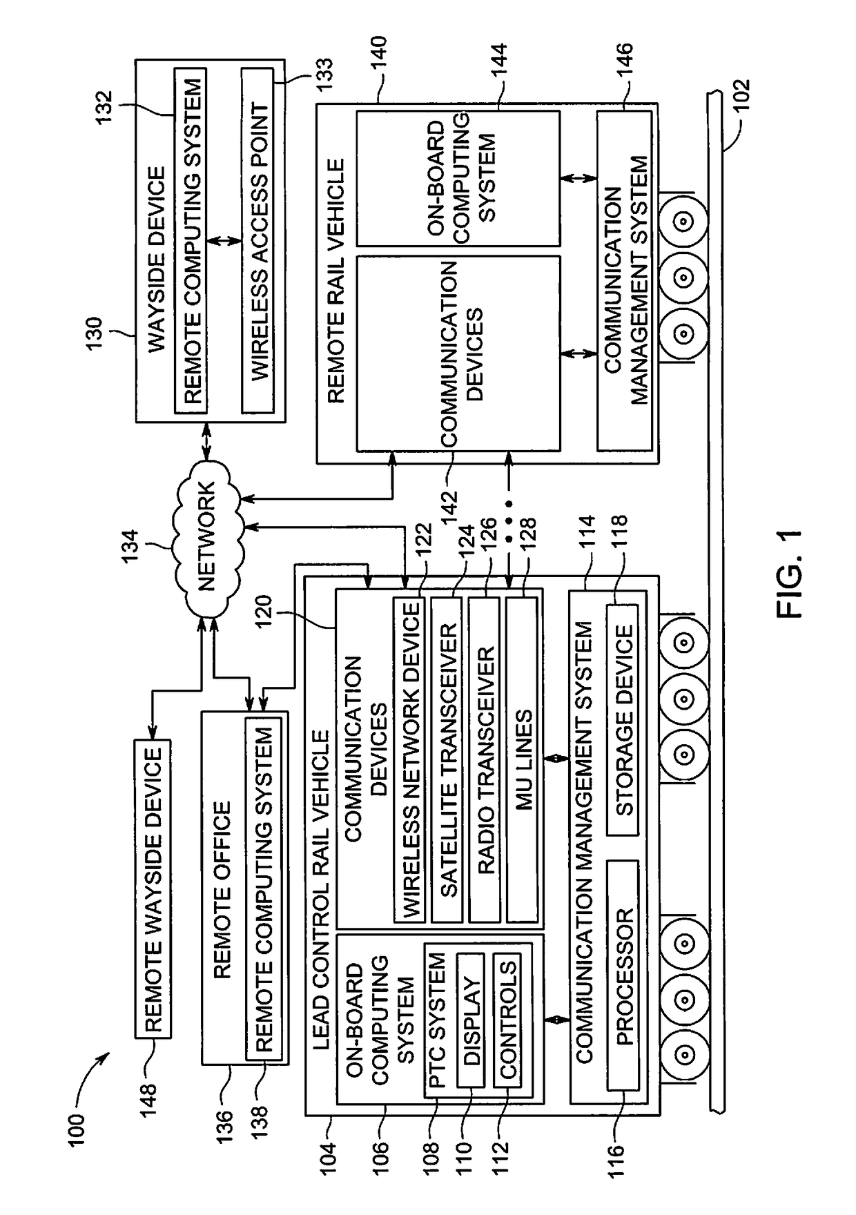
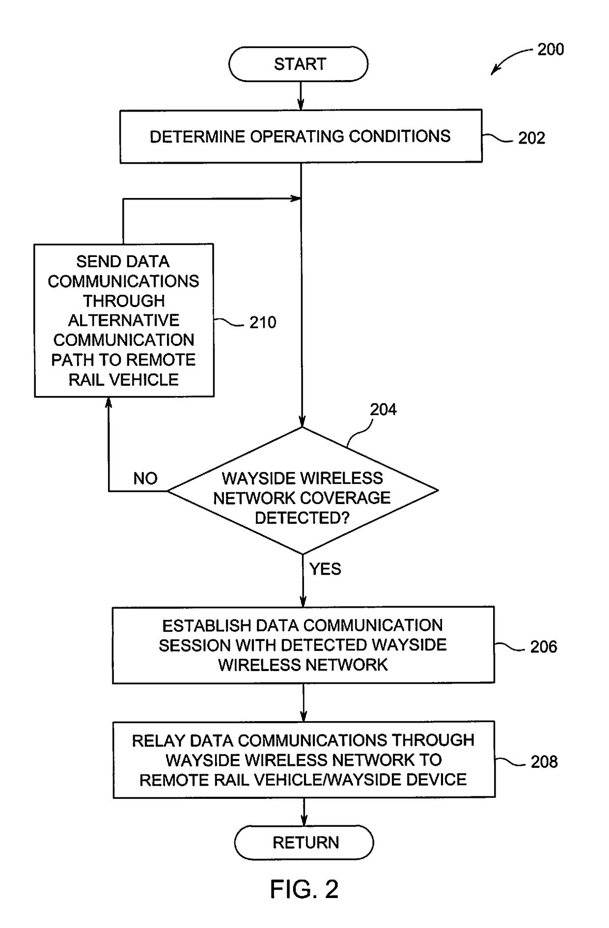
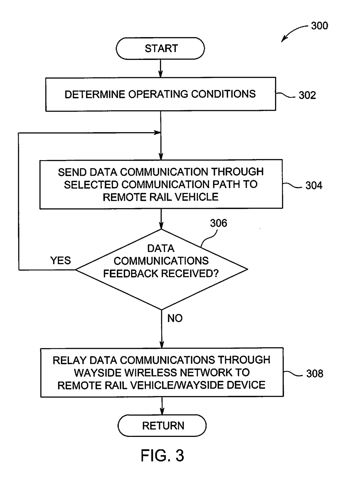
[0023]The present disclosure is directed to systems and methods for data communications between remote rail vehicles of a multiple-unit rail vehicle configuration. More particularly, the present disclosure is directed to systems and methods for providing data communications through different data paths based on operating conditions. For example, in a multiple-unit rail vehicle configuration where a lead control rail vehicle remotely controls operation of the other rail vehicles, data communications are sent from the lead control rail vehicle directly to the other rail vehicles through a dedicated, narrow-band radio link, or the data communications are sent relayed through a wireless network provided by a wayside device to the remote rail vehicles based on operating conditions. In one example, data communications are relayed through the wireless network provided by the wayside device in response to not receiving a confirmation from a remote rail vehicle of receiving a data communicat...


PUM


Abstract

A communication system includes a first wireless communication device disposed onboard a vehicle system having two or more propulsion-generating vehicles that are mechanically interconnected with each other. The communication system also includes a controller configured to be disposed onboard the vehicle system and operatively connected with the first wireless communication device in order to control operations of the device. The controller is configured to direct the first wireless communication device to switch between operating in an off-board communication mode and an onboard communication mode. When the first wireless communication device is operating in the off-board communication mode, the device is configured to receive remote data signals from a location that is disposed off-board of the vehicle system. When the first wireless communication device is operating in the onboard communication mode, the device is configured to communicate local data signals between the propulsion-generating vehicles of the vehicle system.

Description

CROSS-REFERENCE TO RELATED APPLICATIONS[0001]This application is a continuation-in-part of U.S. patent application Ser. No. 12 / 948,053, which was filed on 17 Nov. 2010, and is titled “Methods And Systems For Data Communications” (the “'053 application”). This application also is a continuation-in-part of U.S. patent application Ser. No. 13 / 729,446, which was filed on 28 Dec. 2012, and is titled “Signal Communication System And Method For A Vehicle System” (the “'446 application”). The entire disclosures of the '053 application and the '446 application are incorporated by reference.FIELD[0002]The present disclosure is directed to methods and systems for controlling rail vehicle data communications.BACKGROUND[0003]A set of vehicles under multiple-unit (MU) control, such as a consist of rail vehicles, includes a plurality of vehicles for providing power to propel the consist that are controlled from a single location. Typically, the vehicles are spread throughout the consist to provide...

Claims


Application Information

Patent Timeline
Patent Type & Authority Patents(United States)
IPC IPC(8): G06F19/00B61L15/00B61L27/00
CPCB61L15/0027B61L27/0088B61L27/0005B61L15/0081B61L27/53B61L27/70
Inventor COOPER, JARED KLINEMANFOY, ROBERT JAMESPELTZ, DAVID MICHAELSMITH, EUGENEKELLNER, STEVEN ANDREWSCHROECK, BRIAN WILLIAMGILBERTSON, KEITHNOFFSINGER, JOSEPH FORRESTDAUM, WOLFGANG
Owner GE GLOBAL SOURCING LLC
Learn More