Beam generation unit and X-ray small-angle scattering apparatus

a beam generation unit and x-ray technology, applied in material analysis using wave/particle radiation, instruments, nuclear engineering, etc., can solve the problem of large apparatus size, inability to simultaneously obtain anisotropic patterns by a one-dimensional detector, and the nature of x-ray to tend to diverge, etc., to achieve high signal-to-background ratio

Active Publication Date: 2018-12-04
RIGAKU CORP
View PDF16 Cites 2 Cited by
  • Summary
  • Abstract
  • Description
  • Claims
  • Application Information

AI Technical Summary

Benefits of technology

[0022]According to the present invention, the channel-cut monochromator crystals are arranged in the arrangement of (+, −, −, +) in the rear stage of the slit, and therefore, it is possible to simultaneously obtain anisotropic images in a high signal-to-background ratio with a compact configuration.

Problems solved by technology

However, in such an apparatus, it is necessary to provide a distance between the slits, and therefore, an apparatus with large dimensions is necessary.
However, it is not possible to simultaneously obtain anisotropic patterns by a one-dimensional detector or a two-dimensional detector.
However, with such an apparatus, the nature of the X-ray to tend to diverge is left and the beams spread because the tail is not removed sufficiently.
The reason is that the channel-cut monochromator crystals can be arranged only in arrangement of (+, −, +, −) and therefore, it is not possible to remove the tail caused by the spatial divergence.

Method used


Image

  • Beam generation unit and X-ray small-angle scattering apparatus
  • Beam generation unit and X-ray small-angle scattering apparatus
  • Beam generation unit and X-ray small-angle scattering apparatus

Examples


first embodiment

[0031][First Embodiment]

[0032](X-Ray Small-Angle Scattering Apparatus)

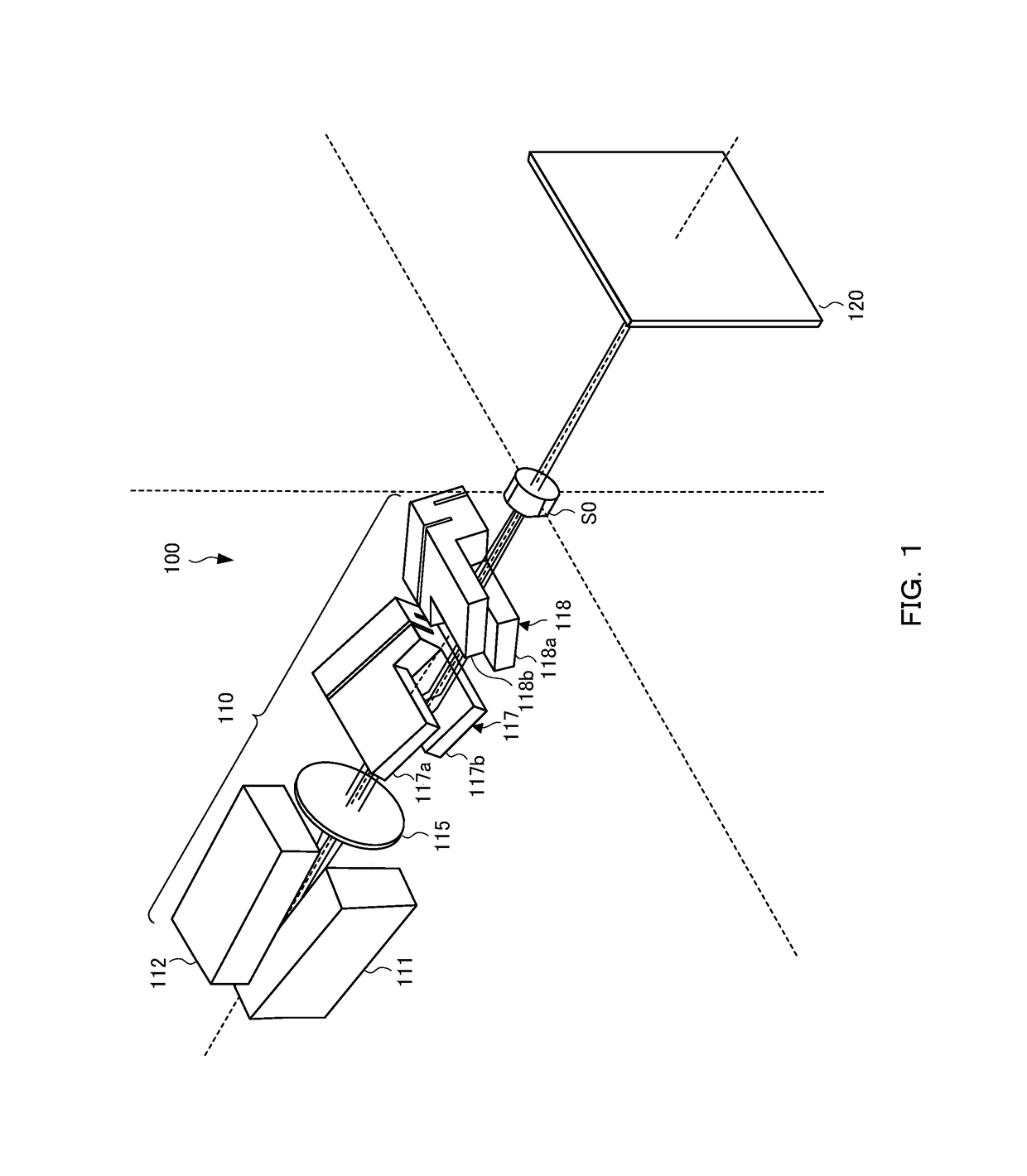
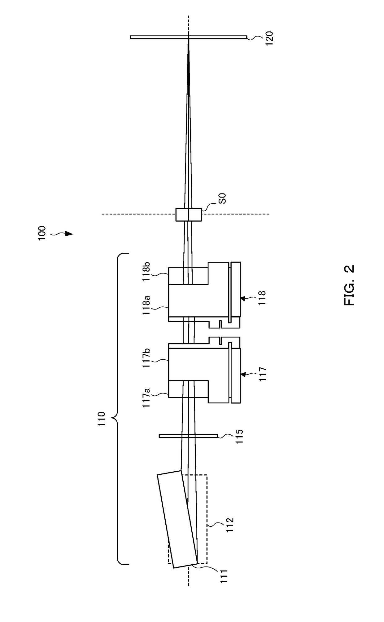
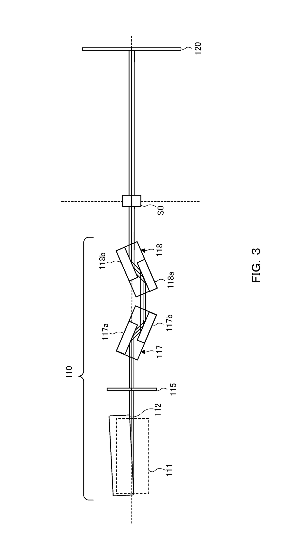
[0033]X-ray small-angle scattering is a method of analyzing the structure of a substance by measuring scattered X-rays whose scattering angle is small (normally, 10° or less) among scattered X-rays when the substance is irradiated with X-rays. If the wavelength of the X-ray is taken to be λ, the scattering angle is taken to be 2θ, from Bragg's law λ=2d sin θ, measuring scattered X-rays whose scattering angle is smaller corresponds to measuring a larger structure in the real space. Common sizes measured by the small-angle scattering are 1 to 100 nm, and therefore, it is possible to analyze a structure at the level of several nanometers, such as internal structures of a fine particle, a liquid crystal, and an alloy, by the small-angle scattering.

[0034]FIG. 1 to FIG. 3 are a perspective view, a side view, and a plan view, respectively, showing an outline of an X-ray small-angle scattering apparatus 100. As shown in F...

example)

[0077](Example)

[0078]Spectrum measurement of X-ray beams generated by the above-described beam generation unit (example) and by 4-crystal and 2-crystal beam generation units (comparative examples) was performed. FIGS. 4 (a) to 4 (d) are plan views each showing a configuration of beam generation unit. The distance from the X-ray source to the detection position is set to 750 mm in each configuration.

[0079]FIG. 4 (a) shows a configuration of a beam generation unit using a slit, in which two channel-cut monochromator crystals are arranged so as to be in the arrangement of (+, −, −, +) in the rear stage of the incident slit 115, 0.1 mm wide, and X-rays are collimated. As the X-ray source, the CuKα-rays are used, as the channel-cut monochromator crystal, the dispersive Ge crystal is used, and Ge (220) is used as the crystal plane (this also applies to the following comparative examples). The collimated X-rays are scanned and detected by a beam-receiving slit 130, 0.1 mm wide.

[0080]In pla...


PUM

PropertyMeasurementUnit
lengthaaaaaaaaaa
heightaaaaaaaaaa
heightaaaaaaaaaa

Abstract

A micro beam generation unit capable of simultaneously capturing anisotropic images in a high signal-to-background ratio with a compact configuration and an X-ray small-angle scattering apparatus are provided. A micro beam generation unit 110 generates X-rays having a micro spot size, with which a sample is irradiated, in order to detect diffracted X-rays by a one-dimensional detector or a two-dimensional detector. The micro beam generation unit 110 includes a slit 115 that is provided on an X-ray optical path and reshapes X-rays into parallel beams, and two channel-cut monochromator crystals 117 and 118 that are arranged in arrangement of (+, −, −, +) and remove parasitic scattering of parallel beams reshaped by the slit. Accordingly, it is possible to simultaneously obtain anisotropic images in a high signal-to-background ratio with a compact configuration.

Description

TECHNICAL FIELD[0001]The present invention relates to a beam generation unit that generates X-rays with which a sample is irradiated in order to detect scattered X-rays or diffracted X-rays, and an X-ray small-angle scattering apparatus.BACKGROUND ART[0002]Conventionally, an apparatus configuration for forming parallel X-ray beams by arranging three slits is known as an apparatus for measuring X-ray small-angle scattering because of a need of irradiation of X-rays whose scattering angle is small in X-ray small-angle scattering measurement (Patent Document 1, Non-Patent Document 1). A slit is used to form thin beams, but when X-ray beams hit the end of the slit, parasitic scattering occurs and a tail is left in the scattering angle direction outside the generated beams. In the apparatus with three slits, parasitic scattering is removed by the second and third slits provided with a distance in between. However, in such an apparatus, it is necessary to provide a distance between the sl...

Claims


Application Information

Patent Timeline
Patent Type & Authority Patents(United States)
IPC IPC(8): G01N23/201G21K1/10G21K1/06
CPCG01N23/201G21K1/06G21K1/10G01N2223/315G01N2223/054G01N2223/056G01N23/207
Inventor OMOTE, KAZUHIKOITO, KAZUKI
Owner RIGAKU CORP
Why Eureka
Try Eureka