Pressurising of bulk material in lock hoppers

a technology of bulk material and lock hopper, which is applied in the direction of bulk conveyor, gasifier moving parts, combustible gas production, etc., can solve the problems of reducing the flowability of blow bottles, requiring complex feeding devices, and not being usable at all, so as to reduce the pressure time and alleviate noise nuisances

Active Publication Date: 2018-12-11
PAUL WURTH SA
View PDF18 Cites 2 Cited by
  • Summary
  • Abstract
  • Description
  • Claims
  • Application Information

AI Technical Summary

Benefits of technology

[0013]An enhanced way for pressurizing bulk material in so-called lock hoppers is provided herein, which process allows reducing the pressurizing time needed, resolving the above-mentioned dimensioning issue of the equipment and / or alleviating noise nuisances compared to existing processes and installations.

Problems solved by technology

Indeed, such blow bottles being constantly operated under pressure require complex feeding devices often consisting of a cascade of pressure resistant feeding units with transitional zones under increasing pressure.
Especially for systems operating at high pressures such blow bottles are either not usable at all or become too complex and unreliable.
An important aspect of such installations is that the initial difference in gas pressure between the process gas supply main or the buffer vessel and the lock hopper is generally so high that it would lead to initially very huge gas velocities leading to compacting the bulk material inside the lock hopper, thereby reducing its flowability and thus preventing the subsequent emptying of the hopper.
So, although the time needed to pressurize the lock hopper should be kept as short as possible in order not to be a limiting factor in the downstream process in common plants, the initial flow rates in the pressurizing gas branches are generally limited.
The main disadvantages of existing installations remain the too long duration needed for fully pressurizing bulk material in the lock hopper, the dimensioning of certain parts of the equipment to cope with initial pressurizing conditions and / or the noise nuisance during the process.

Method used


Image

  • Pressurising of bulk material in lock hoppers
  • Pressurising of bulk material in lock hoppers

Examples


Embodiment Construction

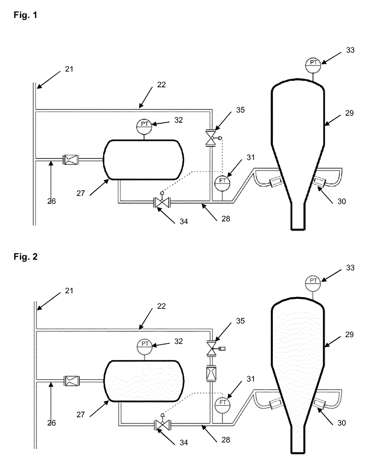
[0038]With reference to FIG. 1, an apparatus for pressurizing bulk material in a hopper configured as a lock hopper 29 is provided for containing a bulk material, such as coal powder. A number of lines 22, 26, 28 are provided to convey the pressurized gas from the source (directly or via a buffer vessel) to one or more inlets 30 of the lock hopper 29. A controllable valve 34, 35 is arranged in the lines and its opening position may be controlled by a control unit (not represented separately). This control unit is programmed to control the opening position of the valve in order to provide pressurizing gas to the lock hopper at a preset constant gas volume flow rate, thus producing constant pressurizing gas actual velocities in the piping, the sintered metal discs 30 and the bulk material inside the lock hopper 29.

[0039]The gas flow rate control valve (controllable valve) may be operated in two different ways, both ways resulting in the constant gas volume flow rate aimed at (both way...


PUM

PropertyMeasurementUnit
initial pressureaaaaaaaaaa
pressureaaaaaaaaaa
volumeaaaaaaaaaa

Abstract

A process for pressurizing bulk material in a hopper; wherein the hopper is configured as a lock hopper (29) containing a bulk material, a source of pressurized gas, lines (22, 26, 28) to convey the pressurized gas from the source to one or more inlets (30) of the lock hopper, a valve arranged in the lines, wherein the opening position of said valve (34, 35) is controlled to provide pressurizing gas to the lock hopper at a preset constant gas volume flow rate.

Description

TECHNICAL FIELD[0001]The present invention generally relates to transporting bulk solid material, over larger distances, such as in so-called dense phase conveying, and / or against a considerable back-pressure.BACKGROUND ART[0002]In upstream pneumatic conveying lines transporting bulk solid material, especially pulverized material, over larger distances, particularly in so-called dense phase conveying, and / or against a considerable back-pressure at the outlet of the conveying line(s), the overpressure required in order to feed the bulk material into the line(s) may be significant.[0003]In these circumstances, the inward transfer of the bulk material is commonly performed by means of hoppers designed as pressure vessels and usually called conveying hoppers, feed hoppers, blow tanks, etc. In the frequent cases where a continuous supply of bulk material to the downstream consumer is requested, at least two of those hoppers are provided, either in a serial arrangement or in a parallel ar...

Claims


Application Information

Patent Timeline
Patent Type & Authority Patents(United States)
IPC IPC(8): B65G53/18C10J3/50B65G53/66B65G53/46B65G53/12
CPCC10J3/506B65G53/12B65G53/4616B65G53/66C10J2200/36C10J3/50C10J2200/156B65G2812/1641
Inventor SCHMIT, LOUISMULLER, BEN
Owner PAUL WURTH SA
Why Eureka
Try Eureka