Assembly of a crankshaft end portion with a flywheel and a guide bearing, and related engine assembly

a technology of flywheel and guide bearing, which is applied in the direction of bearings, shafts, shaft assemblies, etc., can solve the problems of assembly, stressing the plain bearing, and high tension on the accessory drive belt, and achieve the effect of reducing the axial size of the assembly

Inactive Publication Date: 2018-12-18
TORRINGTON COMPANY
View PDF8 Cites 0 Cited by
  • Summary
  • Abstract
  • Description
  • Claims
  • Application Information

AI Technical Summary

Benefits of technology

[0007]The assembly thus defined, by eliminating the collar of the prior art, allows mounting of a single-piece guide ring, which may be a single-piece annular shell of a plain bearing, an inner ring or a mixed ring. By disposing the axial bores on the ring, the elimination of the collar does not take place to the detriment of the surface area available for the position of the fixing screws. It is thus possible to provide fixing screws in a sufficient number to limit the shear forces on each screw. Finally, elimination of the collar reduces the axial size of the assembly.

Problems solved by technology

The recent development in internal combustion engines with low fuel consumption towards engine speeds with a low rotation speed and high engine torque, with intermittent functioning in stop / start mode, causing high tension on the accessory drive belt, and interruptions in the oil pump, greatly stresses the plain bearings, in particular on start-up and during transient periods when cold.
A problem of assembly is then encountered, because of the confinement of the journal between the collar and the first crank of the crankshaft, which requires either an inner bearing ring in two parts, a solution that is not very efficient, or a rolling path formed directly on the crankshaft, as suggested in the document FR 2 906 167.
This solution is particularly expensive and does not make it possible to optimise the choice of material forming the rolling path.
Another solution would consist of eliminating the collar, but with the drawback of considerably reducing the surface area available for fixing the flywheel to the crankshaft, and therefore reducing the number of fixing screws, but also of reducing the screw fixing diameter and therefore, for a given nominal torque, increasing the shear forces undergone by each screw.

Method used


Image

  • Assembly of a crankshaft end portion with a flywheel and a guide bearing, and related engine assembly
  • Assembly of a crankshaft end portion with a flywheel and a guide bearing, and related engine assembly
  • Assembly of a crankshaft end portion with a flywheel and a guide bearing, and related engine assembly

Examples


first embodiment

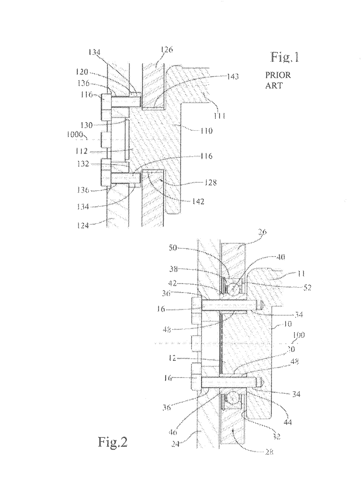
[0025]In FIG. 2 an assembly according to the invention is illustrated, comprising a crankshaft 10 guided for rotation in an engine casing 26 by means of a guide bearing 28, to which a flywheel 24 is fixed by fixing screws 16.

[0026]The crankshaft 10 comprises cranks 11 and an end portion 12, which forms a first bearing surface 30, here cylindrical, turned radially outwards, and a shoulder 32 on which threaded axial holes 34 emerge. The flywheel 24 comprises a plurality of axial bores 36 aligned with the threaded axial holes 34 in the end portion 12 of the crankshaft. The guide bearing 28 provides the rotational guidance of the crankshaft and of the flywheel 24 about an axis of revolution 100 and is composed of an outer bearing ring 38 mounted with a tight fit in an opening 50 in the engine casing 26, in abutment against a shoulder 52 of the opening, rolling bodies 40 and an inner bearing ring 42. The inner bearing ring 42 has two transverse abutment faces 44 and 46 and is also pierce...

second embodiment

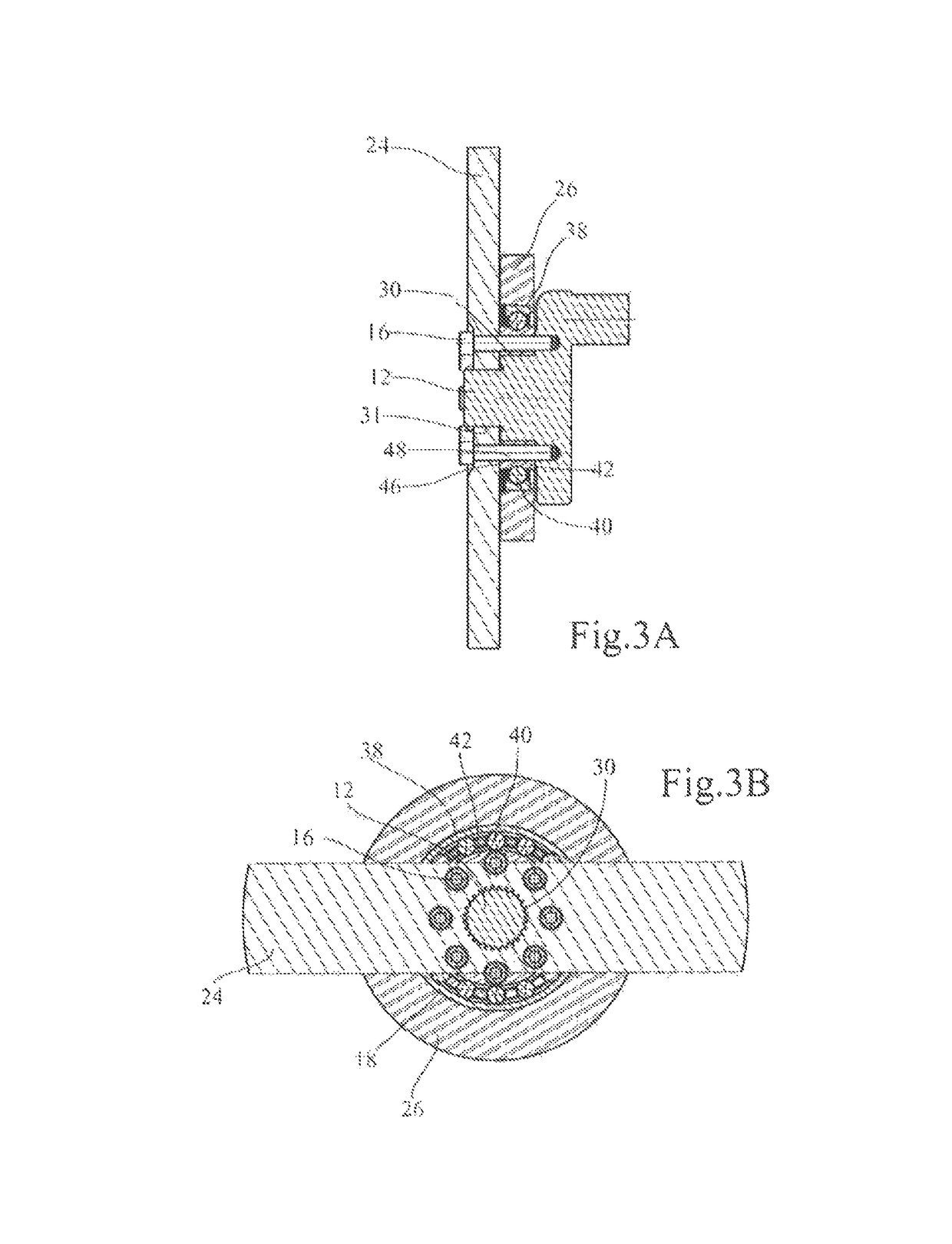
[0028] illustrated in FIGS. 3A and 3B, the end portion 12 of the crankshaft is substantially longer and the flywheel is slid onto a second bearing surface 31 through a central bore, the inwardly turned radial surface of which is complementary to the surface of the second, cylindrical, bearing surface 31, fluted or other. As before, the flywheel comes into abutment on the transverse face 46 of the inner ring of the rolling bearing for secure fixing with the crankshaft.

third embodiment

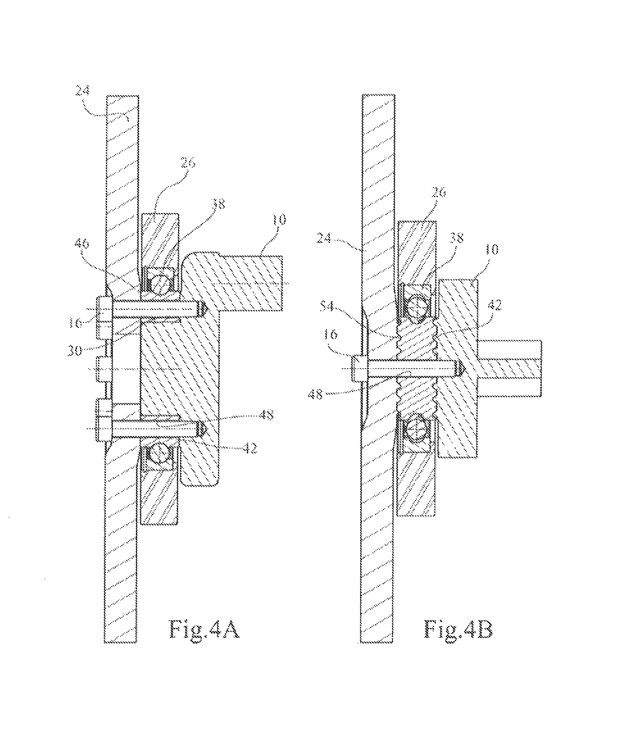
[0029] illustrated in FIGS. 4A, 4B and 4C, the transverse face 46 of the inner ring 42 is provided with reliefs, which may for example be radial grooves 54 distributed over the entire circumference or over one or more angular sectors, and in which conjugate reliefs are inserted, for example corresponding radial ribs formed on the flywheel 24.


PUM


Abstract

To assemble an end portion (12) of a crankshaft (10) defining an axis (100) of revolution, forming at least one first bearing surface (30), turned radially outward, and a shoulder (32), on which threaded holes (34) lead outward, with a flywheel (24) comprising axial bores (36) and a bearing (28) for guiding the crankshaft relative to an engine housing (26) in rotation about the axis of revolution, attachment screws (16) passing through the axial bores of the flywheel and screwed into the threaded holes in the crankshaft end portion are provided, thus rigidly connecting the flywheel to the crankshaft end portion. The guide bearing comprises at least one unitary guide ring (42) positioned on the first bearing surface (30) and having a first transverse surface (44) axially bearing on the shoulder (32). The unitary guide ring comprises axial bores (48) which are aligned with the threaded holes (34) in the crankshaft and the axial bores of the flywheel (36) and have the screws (16) passing therethrough.

Description

CROSS-REFERENCE TO RELATED APPLICATIONS[0001]This application is the National Stage entry under 35 U.S.C. § 371 of international Application Number PCT / FR2016 / 051879 filed on Jul. 20, 2016, published on Jan. 26, 2017 under publication number WO 2017 / 013359 A1, which claims the benefit of priority under 35 U.S.C. § 119 of French patent application number 1556894 filed Jul. 21, 2015.TECHNICAL FIELD OF THE INVENTION[0002]The invention relates to coaxial assembly between a flywheel and a crankshaft, integrating a guide bearing.PRIOR ART[0003]According to the prior art illustrated in FIG. 1, a crankshaft 110 of an internal combustion engine has an end portion 112 guided for rotation about an axis of revolution 100 with respect to an engine casing 126 by means of a plain bearing 128, this end 112 comprising a collar 120 projecting outside the engine casing 126. The collar 120 forms a positioning surface 130 turned radially outwards and a shoulder 132 on which threaded holes 134 emerge, an...

Claims


Application Information

Patent Timeline
Patent Type & Authority Patents(United States)
IPC IPC(8): F16F15/31F16C33/36F16C9/02F16C35/067F16F15/315
CPCF16F15/3153F16C9/02F16C33/363F16F15/3156F16C35/067F16C2360/22F16C2226/60
Inventor PAQUIEN, MARC
Owner TORRINGTON COMPANY
Why Eureka
Try Eureka