
Coordinate indicator

Inactive Publication Date: 2006-03-23
WACOM CO LTD
View PDF5 Cites 16 Cited by
  • Summary
  • Abstract
  • Description
  • Claims
  • Application Information

AI Technical Summary

Benefits of technology

[0009] Accordingly, in a coordinate indicating device used for an input device of electronic equipment, it is an object of the present invention to achieve miniaturization of the entire coordinate indicating device by reducing components in size, as well as to secure resistivity to impact and high reliability.

Problems solved by technology

Hence, brittleness of the ferrite is a very important problem, so that overcoming this problem may lead to the miniaturization of the pen-shaped coordinate indicating device to the large extent.
However, miniaturization of the electronic instruments, especially of portable instruments, is progressing even now, so that miniaturizing the pen tablet is further strongly demanded.
However, the smaller the ferrite core becomes in size, a disadvantageous problem arises in resistivity to impact.

Method used


Image

  • Coordinate indicator
  • Coordinate indicator
  • Coordinate indicator

Examples


example

(2)

[0103] In Example (1), the ferrite core 122 used L6 member (made by TDK Corporation), and was shaped in a cylinder with external diameter 1.6 mm and length 3 mm.

[0104] In the graph shown in FIG. 4, the loads applied to the coordinate indicator 11 are plotted in abscissa and the writing force levels detected by the coordinate input device 1 are plotted in ordinate.

[0105] The change in writing force level detected by the tablet 20 is based on the change in inductance of the coil 116 as described above. Hence, the changes in ordinate of the graph are indirectly assumed to be changes in inductance of the coil 116.

[0106] In any of Examples (1) and (2) shown in FIG. 4, the detected writing force level obviously varies in accordance with the load to the coordinate indicator 11, so that it accurately detects the change in load applied to the coordinate indicator 11.

[0107] In the Examples shown in FIG. 4, when the load applied to the coordinate indicator 11 changes in a range of 0 to ...


PUM


Abstract

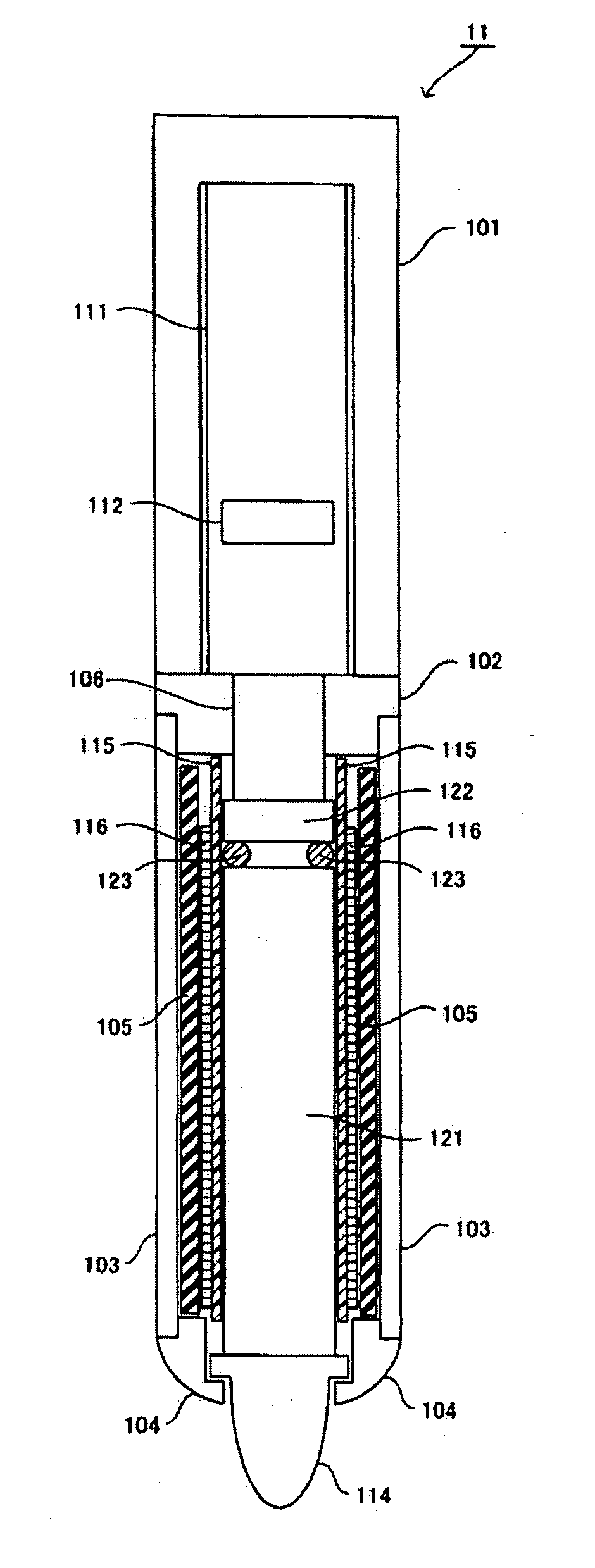
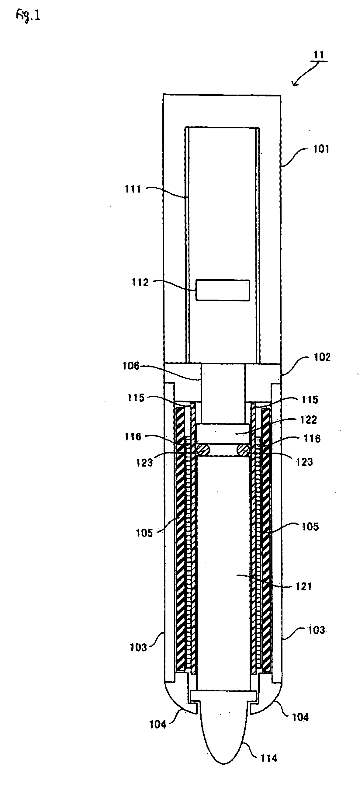
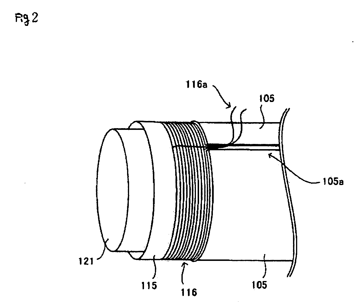
In a coordinate indicator used for an input device of electronic equipment, to miniaturize the entire indicator as well as to secure resistance to impact and reliability by reducing components in size. A coordinate indicator includes a casing composed of an upper case, a substrate holder, a ceramic pipe, and an edge case; a center core, a ferrite core A moving together with the center core during operation, and a ferrite core B fixed to oppose the ferrite core A, which are accommodated within the casing. Around a tube accommodating part of the ferrite core A and the entire ferrite core B therein, a coated conducting wire is wound so as to form a coil.

Description

CROSS-REFERENCE TO RELATED APPLICATION AND CLAIM TO PRIORITY [0001] Applicants hereby claim priority under 35 U.S.C. §119 to Japanese Application No. 2004-250269, filed Aug. 30, 2004, titled “Coordinate Indicator”, the disclosure of which is incorporated herein by reference. FIELD OF THE INVENTION [0002] The present invention relates to a coordinate indicating device used for input devices in electronic equipment such as computers. BACKGROUND OF THE INVENTION [0003] A pen tablet has been known as an input device for various electronic instruments such as computers. Because the pen tablet can be reduced in size compared to a key board, the application to a compact electronic instrument, such as a PDA (personal digital assistant), is expected, and the miniaturizing of the pen tablet is also demanded. [0004] Other patent applications assigned to the same assignee as this application have proposed various techniques for miniaturizing a pen-shaped coordinate indicating device (so-called ...

Claims


Application Information

Patent Timeline
IPC IPC(8): G06F3/033
CPCG06F3/046G06F3/03545
Inventor FUKUSHIMA, YASUYUKIFUJITSUKA, HIROYUKI
Owner WACOM CO LTD
Learn More