

Single wire steel cord
A technology of steel cord and single wire, which is applied in the direction of wire material processing, manufacturing rings and tires from wire, etc., can solve the problem of cord torsional arc height dependence, and achieve the effects of improving torsion, increasing elongation at break, and improving impact resistance
Inactive Publication Date: 2010-09-29
HYOSUNG CORP
View PDF3 Cites 4 Cited by
- Summary
- Abstract
- Description
- Claims
- Application Information
AI Technical Summary
Problems solved by technology
[0005] However, in the case of known cords having a strand structure (1×n) or single-wire steel cords comprising monofilaments with a circular cross-section, there is a problem that the rotation or camber of the cord is very high. Much depends on the material of the wire or on machines such as drawing machines or stretching machines
Method used
View moreImage
Smart ImageViewing Examples

Examples
example 1
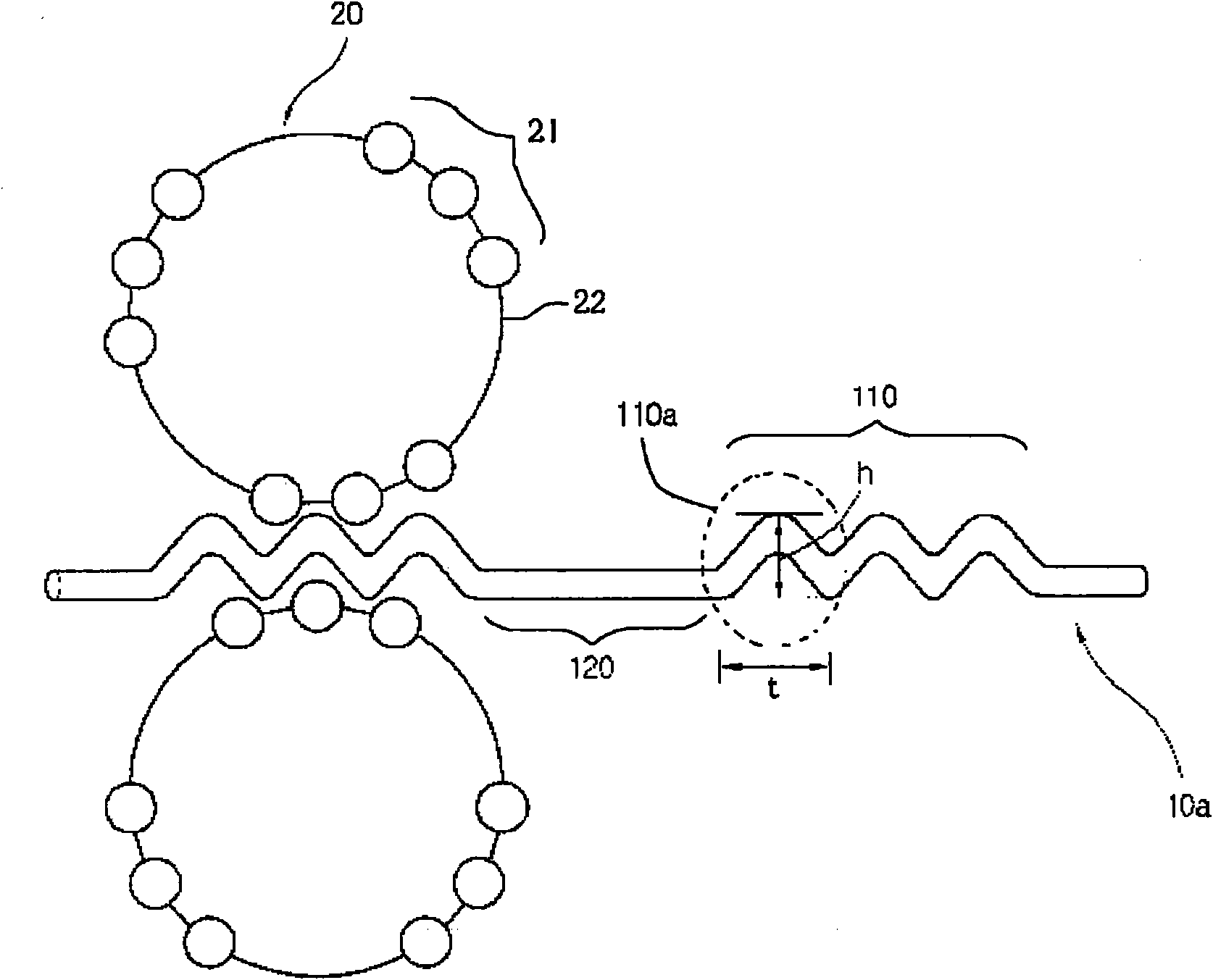
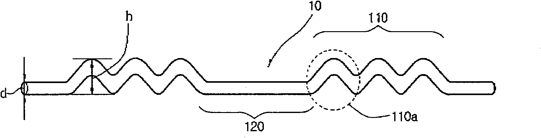
[0038] A wire rod having a carbon content of 0.82% and a diameter of 5.5 mm was first drawn to have a wire diameter of 1.90 mm, then quenched and brass plated. Then, it was subjected to a second drawing treatment so as to have a diameter of 0.40 mm to prepare a monofilament. Next, corrugations were formed on partial regions of the monofilament using a helical device so that each corrugated region included four corrugations and had a length of 10 mm, and each non-corrugated region had a length of 10 mm. Steel cords were produced using straightening R / O, and their physical properties were evaluated. The results are shown in Table 1 below.
Login to View More PUM
| Property | Measurement | Unit |
|---|---|---|
| height | aaaaa | aaaaa |
| length | aaaaa | aaaaa |
| diameter | aaaaa | aaaaa |
Abstract
The present invention relates to a single wire steel cord for reinforcing rubber of a pneumatic tire having improved strength and adhesion to rubber and, more particularly, to a single wire steel cord which includes waveform regions having at least one waveform and non-waveform regions. The single wire steel cord has a high strength characteristic. Accordingly, the amount of steel cord is significantly reduced during manufacturing of a tire. As a result, the weight of the tire is reduced and manufacturing cost is lowered due to a simplified manufacturing process.
Description
technical field [0001] The present invention relates to a single wire steel cord for reinforcing rubber of a pneumatic tire, wherein the cord has improved strength and adhesion to rubber. More specifically, the present invention relates to a single wire steel cord comprising a corrugated zone and a non-corrugated zone, the corrugated zone having at least one wave. Background technique [0002] In recent years, due to various factors such as global environmental protection, many studies have been conducted to improve the fuel efficiency of vehicles, and for this purpose, studies to develop lightweight tires are also underway. Therefore, there is an urgent need to develop a slender and lightweight single wire steel cord. [0003] Generally, a steel cord having a 1×n structure is used for a belt layer of a passenger car radial tire. The steel cord having the above structure has high rigidity. On unpaved roads, however, it pushes too much against the tires, which can be uncom...
Claims
Login to View More Application Information
Patent Timeline
 Patent Type & AuthorityApplications(China)
IPC IPC(8): B29D30/48
CPCD07B1/0646D07B2501/2046D07B7/025D07B2201/2008D07B1/0606D07B2205/3057D07B2401/2005B60C9/0007D07B2201/2006B60C9/0057B60C9/0064Y10T428/1241D07B2801/10B29D30/48D07B1/06B21F37/00
Inventor李亨恩金敏按
OwnerHYOSUNG CORP