Specimen tip and tip holder assembly

a technology of holder and specimen tip, which is applied in the direction of instrumentation, engine lubrication, liquid/fluent solid measurement, etc., can solve the problems of not being able to fine-tune the z-axis position, the device is complex and delicate, and the sample cannot be generally allowed to be tilted by more than +/40°, etc., to achieve the effect of reducing the size of the specimen tip, increasing the tilt angle inside the tem, and increasing the specimen tip

Active Publication Date: 2007-11-06
ROPER INDUSTRIES
View PDF3 Cites 17 Cited by
  • Summary
  • Abstract
  • Description
  • Claims
  • Application Information

AI Technical Summary

Benefits of technology

[0013]By forming the tip holder assembly from two parts and providing actuating means, it is possible to displace the tip holder relative to the support perpendicularly to the axis of the support. This makes it possible to adjust the height of the specimen in the TEM, allowing fine-tuning of the eucentric point. In the description that follows, the term “specimen” ordinarily comprises the sample to be investigated, although it may also comprise an additional supporting object such as a mesh or grid, to which the sample is mounted in use. The height adjustment is incorporated into the specimen tip holder assembly and may be manually controlled by the user. This in situ height adjustment enables accurate and consistent setting of the specimen at the eucentric height. This means that whatever the specimen thickness, the height can be set to allow the same area of the specimen to remain in view (even at high magnification) and generally in focus whatever angle the holder is tilted to.
[0032]At this stage the specimen is ready for use in the TEM. However, the size of the assembly may be further reduced by trimming the side portions of the sample and / or mounting grid. This may be performed either before or after mounting the specimen to the specimen tip. Therefore, the method may further comprise the step of removing at least some of the area of the specimen which overhangs or will overhang the specimen tip. Alternatively physically smaller specimens may be used. Each of the above may provide for improved angles of tilt for the specimen when mounted to the tip.

Problems solved by technology

Conventional specimen holders as described above, including those of U.S. Pat. No. 5,225,683, are bulky and, in the confined space within a high-resolution pole piece, do not generally allow the sample to be tilted by more than + / −40°.
However, due to the variation in the thickness of the sample, this technique does not guarantee that the sample is at the eucentric point and it would be advantageous if the z-axis height of the sample could be fine-tuned by the user.
However the device is of a complex and delicate construction and does not provide the ability to fine-tune the Z-axis position of the specimen without moving the specimen in the XY plane also,

Method used


Image

  • Specimen tip and tip holder assembly
  • Specimen tip and tip holder assembly
  • Specimen tip and tip holder assembly

Examples


Embodiment Construction

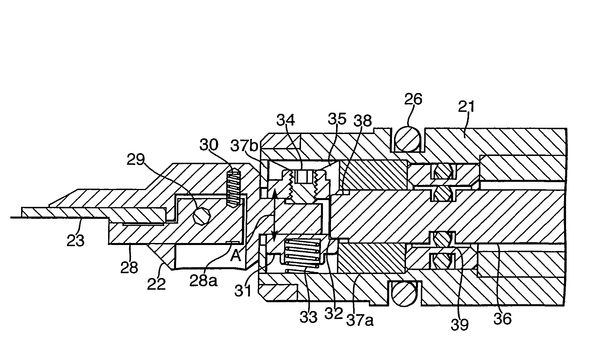
[0048]A specimen tip holder assembly for mounting a specimen tip in a transmission electron microscope (TEM) is illustrated in FIGS. 4, 5 and 6. The assembly 20 consists of a barrel 21, long enough to extend from the exterior of a TEM to the pole piece gap where the sample is positioned in use, and a tip holder 22 coupled to one end of the barrel 21. The tip holder 22 is adapted to support a specimen tip 23. In the Figures, the specimen tip is shown as a separate component, but it is envisaged that the specimen tip 23 could form an integral part of tip holder 22 if so desired. At its other end, the barrel is equipped with a housing 24 designed to fit against the side of a TEM, and a dial 25, discussed below. The assembly 20 is provided with polymeric sealing rings 26 which are fitted around the barrel in such a way that, when placed in a TEM, the passage of gas between the barrel and the TEM is prevented. This enables the TEM to maintain the high vacuum required for successful opera...


PUM


Abstract

A specimen tip holder assembly for mounting a specimen tip in a transmission electron microscope (TEM) is described. The specimen tip holder assembly comprises a tip holder for supporting a specimen tip. The tip holder is coupled to an elongate support for movement in a direction substantially perpendicular to the axis of the support. An actuator is mounted to the support for causing motion of the tip holder relative to the support.

Description

RELATED APPLICATIONS[0001]This application claims the benefit under 35 U.S.C. § 120 of prior application Ser. No. 10 / 903,985, filed on Jul. 30, 2004, by Robert Morrison, now abandoned, which prior application claims priority under 35 U.S.C. §119 from U.K. Ser. No. 0318134.4, filed on Aug. 1, 2003 by Robert Morrison.FIELD OF THE INVENTION[0002]This invention relates to specimen tips and tip holder assemblies for supporting a sample to be analysed in a transmission electron microscope. The invention further provides a method for mounting a specimen to a specimen tip.BACKGROUND OF THE INVENTION[0003]Transmission electron microscopy is a versatile tool widely used across a range of research areas from biology to physio-chemical subjects. The transmission electron microscope is one of the most effective imaging devices available and can be used to study not only the surface morphology but also the internal structure and defects in diverse materials including metals, semiconductors, prote...

Claims


Application Information

Patent Timeline
Patent Type & Authority Patents(United States)
IPC IPC(8): G01F23/00H01J37/20
CPCH01J37/20
Inventor MORRISON, ROBERT
Owner ROPER INDUSTRIES
Why Eureka
Try Eureka