
Adjustable external fixator

a fixator and adjustable technology, applied in the field of adjustable external fixators, can solve the problems of increasing unable to directly adhere to the patient's limb, and serious fracture of bone and soft tissue at the fracture site, so as to reduce the burden on the patient's daily living, reduce the volume, and lighten the weight

Active Publication Date: 2018-12-25
E DA HEALTHCARE GRP
View PDF19 Cites 1 Cited by
  • Summary
  • Abstract
  • Description
  • Claims
  • Application Information

AI Technical Summary

Benefits of technology

The design results in a lighter, more compact external fixator that reduces patient burden and simplifies surgical processes, facilitating bone regeneration and lengthening while maintaining stability and adjustability.

Problems solved by technology

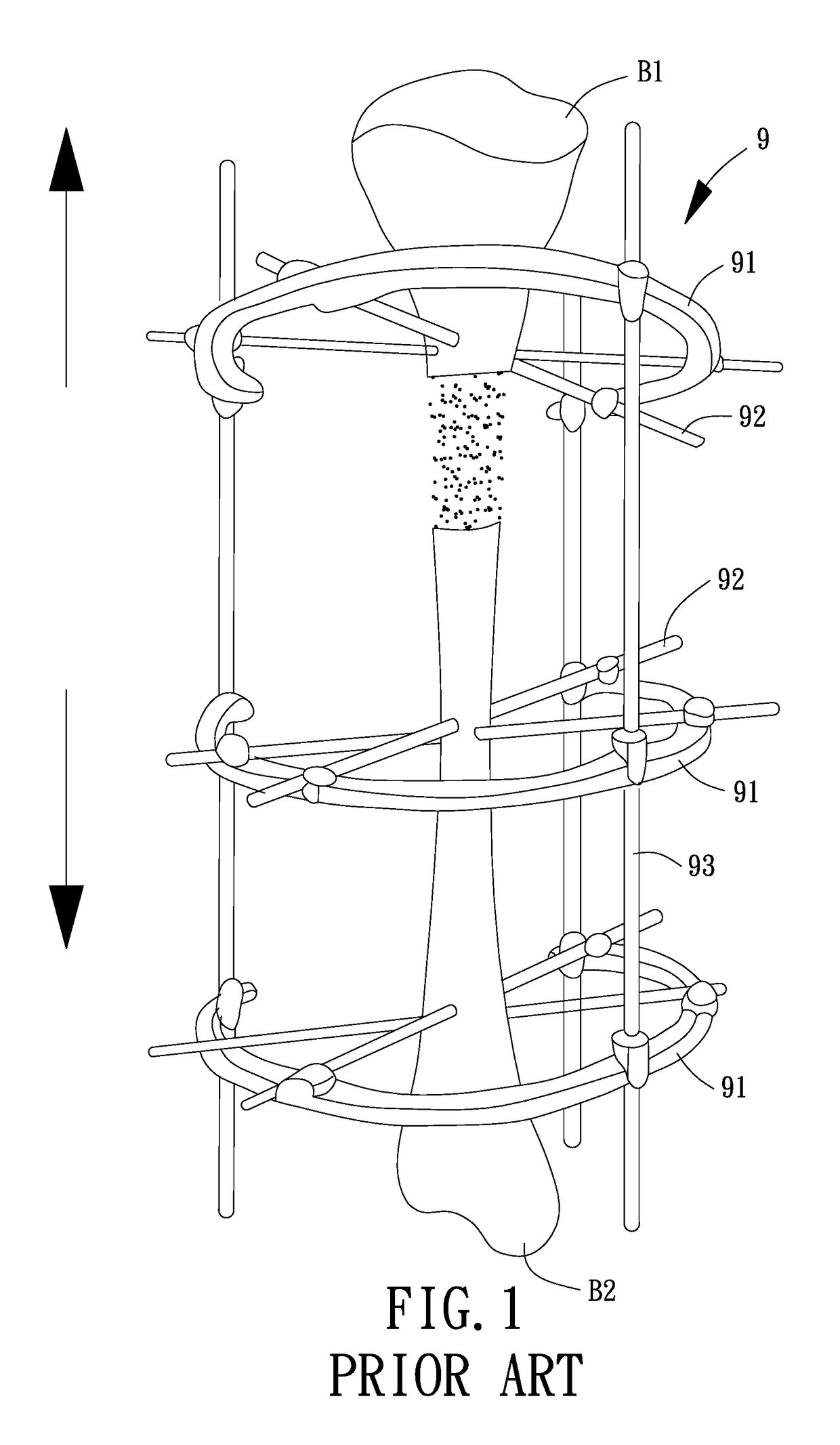
Concerning the treatment of a patient with open bone fracture, after the fracture site is treated and cleaned, some of the bone and soft tissue at the fracture site may be found seriously broken.
However, the conventional adjustable external fixator 9 is fixed around the two bone sections B1 and B2, and the rings 91 cannot directly adhere to the limb of the patient.
Besides, the conventional external fixator 9 has lots of complicated components, resulting in large volume and heavy weight which cause extra burden to daily living of the patient.

Method used


Image

  • Adjustable external fixator
  • Adjustable external fixator
  • Adjustable external fixator

Examples


first embodiment

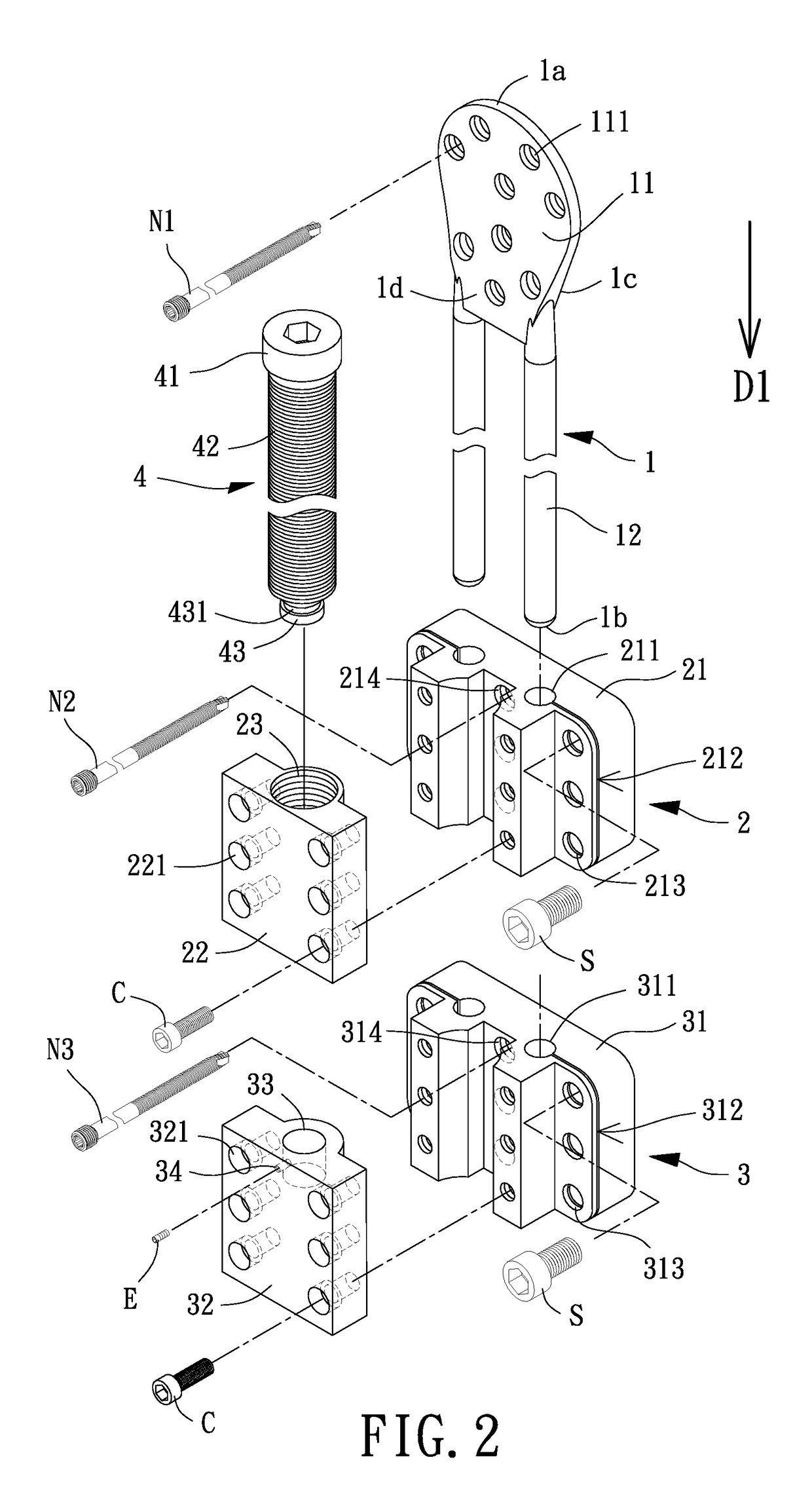
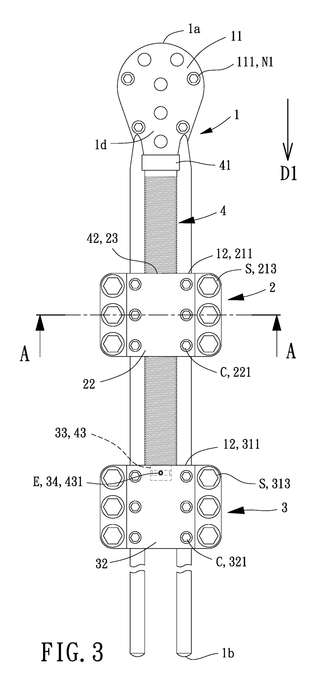
[0027]With references to FIGS. 2-4, an adjustable external fixator according to the present disclosure includes a body 1, a positioning member 2, a bone coupling member 3 and a threaded rod 4.

[0028]Specifically, the body 1 has opposite first and second ends 1a and 1b. The body 1 is preferably arranged parallel to the extending direction of the patient's long bone, such that the bone and soft tissue of the patient can grow in the extending direction of the long bone. For facilitating description of the present disclosure, the body 1 is longitudinally extends from the first end 1a to the second end 1b in a first direction D1. The body 1 further has a coupling side 1c and an adjusting side 1d opposite to the coupling side 1c, with the coupling side 1c and the adjusting side 1d located between the first and second ends 1a and 1b. When the adjustable external fixator is in use, the coupling side 1c of the body 1 can face the limb of the patient.

[0029]The body 1 includes a fixation portio...

second embodiment

[0040]FIG. 5 shows an adjustable external fixator according to the present disclosure. In this embodiment, the bone coupling member 3 does not include a blind hole 33. Hence, the threaded rod 4 can only abut against the bone coupling member 3 via the terminal section 43 (as shown in the figures, the terminal section 43 abuts against an end of the positioning portion 2). Besides, rotating the threaded rod 4 can only make the bone coupling member 3 slide along the slideway 12 in the first direction D1.

[0041]With references to FIG. 6, the adjustable external fixator of the first and second embodiments can be utilized in bone transport. The surgeon can sequentially couple the positioning member 2 and the bone coupling member 3 to the slideway 12 of the body 1, with the positioning member 2 located between the fixation portion 11 of the body 1 and the bone coupling member 3. Next, the surgeon can fix the fixation portion 11 of the body 1 to the bone section B1 via the plurality of first ...


PUM


Abstract

The present disclosure provides an adjustable external fixator which can be utilized in bone transport or bone lengthening. The adjustable external fixator includes a body, a positioning member, a bone coupling member, and a threaded rod. The body includes a slideway. At least one of the positioning member and the bone coupling member is slidably coupled to the slideway of the body.

Description

CROSS REFERENCE TO RELATED APPLICATIONS[0001]The application claims the benefit of Taiwan application serial No. 105110616, filed on Apr. 1, 2016, and the subject matter of which is incorporated herein by reference.BACKGROUND OF THE INVENTION1. Field of the Invention[0002]The present invention generally relates to an adjustable external fixator and, more particularly, to an adjustable external fixator utilized in bone lengthening or bone transport.2. Description of the Related Art[0003]Concerning the treatment of a patient with open bone fracture, after the fracture site is treated and cleaned, some of the bone and soft tissue at the fracture site may be found seriously broken. Hence, the surgeon may attach a conventional adjustable external fixator 9 around the fracture site, such that the bone and soft tissue at the fracture site can steadily regenerate.[0004]With references to FIG. 1, the conventional adjustable external fixator 9 includes a plurality of rings 91, with each ring ...

Claims


Application Information

Patent Timeline
Patent Type & Authority Patents(United States)
IPC IPC(8): A61B17/66A61B17/64A61B17/62A61B17/88A61B17/60A61B17/90
CPCA61B17/645A61B17/62A61B17/6475A61B17/8858A61B17/8872A61B17/66A61B2017/90A61B2017/603A61B17/90
Inventor LIN, TING-SHENGMA, CHING-HOUJIANG, JIUN-RU
Owner E DA HEALTHCARE GRP
Learn More