Refrigerant evaporator

a technology of refrigerant evaporator and liquid phase, which is applied in the direction of indirect heat exchangers, refrigeration components, lighting and heating apparatus, etc., can solve the problems of deteriorating distribution of refrigerant, and achieve the effect of enhancing the distribution of liquid phase refrigerant in the heat-exchanging core portions

Active Publication Date: 2018-12-25
DENSO CORP
View PDF36 Cites 0 Cited by
  • Summary
  • Abstract
  • Description
  • Claims
  • Application Information

AI Technical Summary

Benefits of technology

[0020]The present disclosure has a first object to provide a refrigerant evaporator capable of enhancing distribution of a liquid phase refrigerant.
[0021]The present disclosure has a second object to provide a refrigerant evaporator capable of restricting a generation of a temperature distribution in blown air passing through the refrigerant evaporator when a flow rate of a refrigerant flowing a refrigeration cycle is low.
[0026]Hence, distribution of the liquid phase refrigerant in the heat-exchanging core portions can be enhanced. Consequently, a temperature distribution generated in blown air passing through the refrigerant evaporator can be restricted when a flow rate of a refrigerant flowing a refrigeration cycle is low.
[0029]By providing the dam portion inside the other tank portion of the first evaporation unit to hold back a flow of the liquid phase refrigerant that has flowed into the other tank portion from the refrigerant inlet portion, even when a flow rate of the refrigerant flowing the refrigeration cycle is low, the liquid phase refrigerant can be let into the tubes disposed between the refrigerant inlet portion and the dam portion in a reliable manner.

Problems solved by technology

Consequently, distribution of the refrigerant is deteriorated.

Method used


Image

  • Refrigerant evaporator
  • Refrigerant evaporator
  • Refrigerant evaporator

Examples


first embodiment

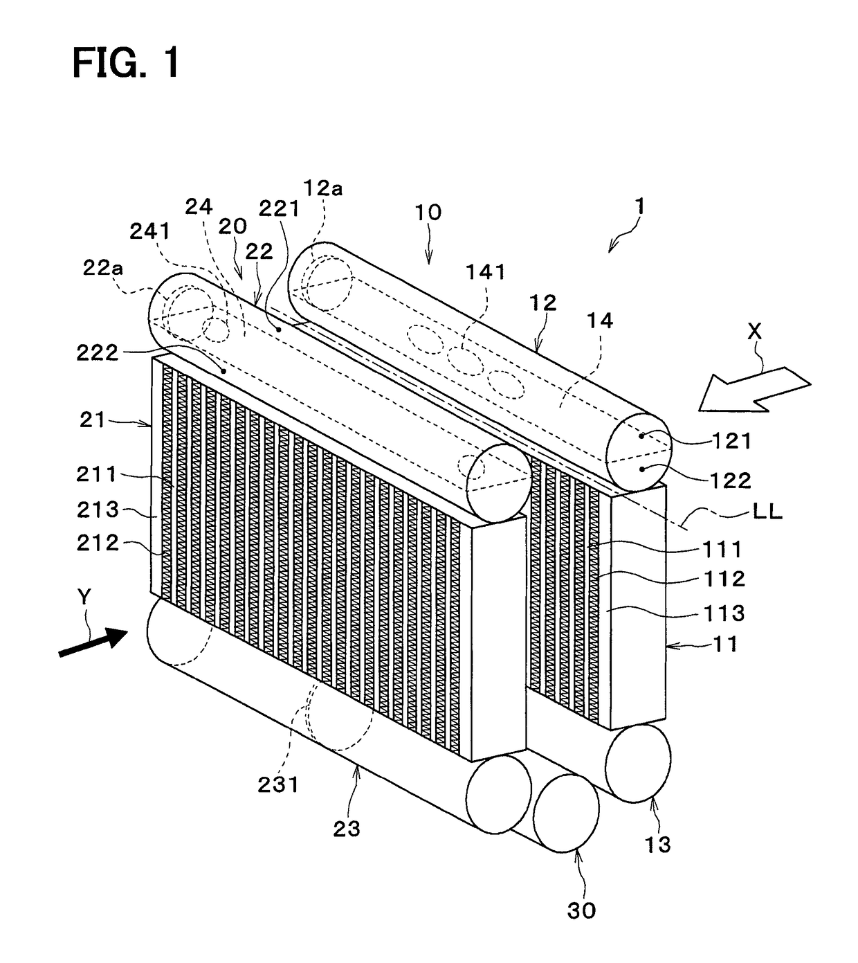
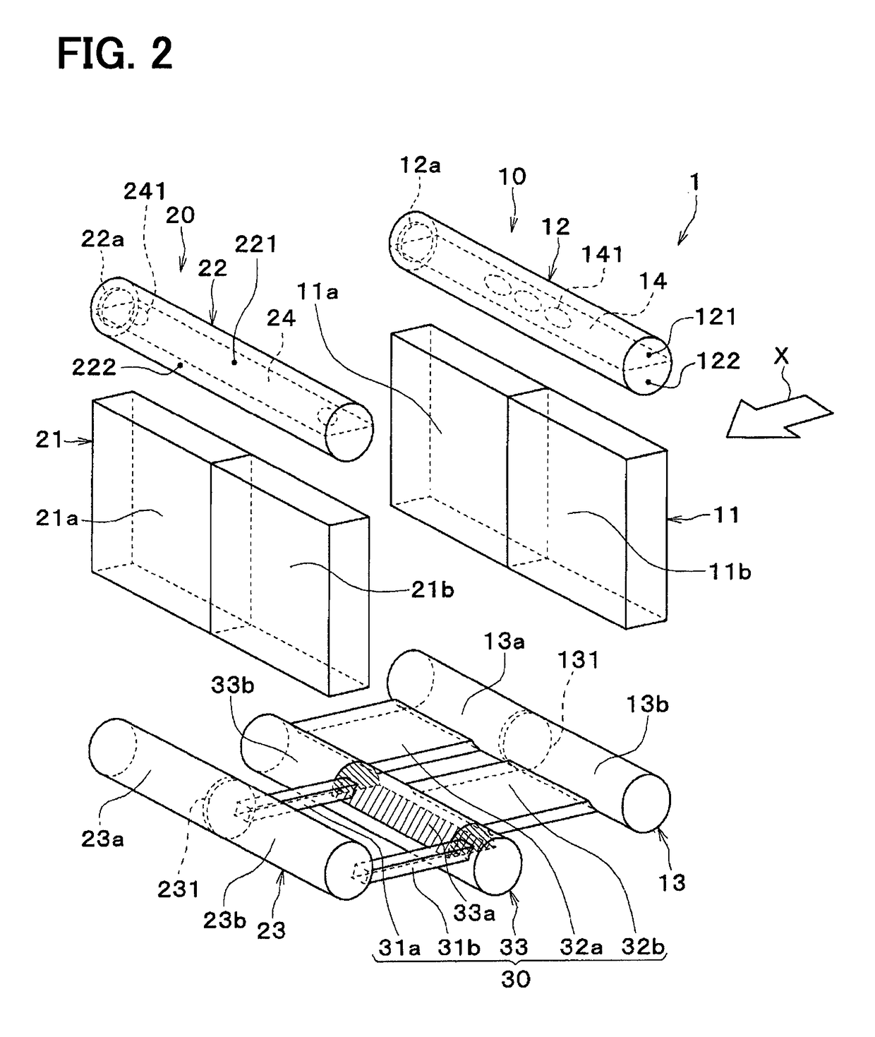
[0053]A first embodiment will be described using FIG. 1 through FIG. 7. A refrigerant evaporator 1 of the present embodiment is a cooling heat exchanger which is applied to a vapor compression refrigerating cycle in an air conditioner for a vehicle to adjust a temperature in the vehicle interior and cools blown air to be blown into the vehicle interior by absorbing heat from the blown air and letting refrigerant (liquid phase refrigerant) evaporate. In the present embodiment, the blown air corresponds to “a fluid flowing outside to be cooled”.

[0054]The refrigerating cycle is known to include the refrigerant evaporator 1 as well as components unillustrated herein, such as a compressor, a radiator (condenser), and an expansion valve. In the present embodiment, the refrigerating cycle is formed as a receiver cycle in which a liquid receiver is disposed between the radiator and the expansion valve. The refrigerant in the refrigeration cycle is mixed with refrigerant oil to supply lubric...

second embodiment

[0122]A second embodiment will be described with reference to FIG. 8. The second embodiment is different from the first embodiment above in a configuration of first communication holes 241 and second communication holes 141.

[0123]As shown in FIG. 8, first communication holes 241a, which are a part of multiple first communication holes 241, are disposed at positions so as to overlap the second communication holes 141 when viewed in a flow direction X of blown air. First communication holes 241b, which are the rest of the multiple first communication holes 241, are disposed at positions so as not to overlap the second communication holes 141 when viewed in the flow direction X of blown air.

[0124]Second communication holes 141a, which are a part of the multiple second communication holes 141, are disposed at positions so as to overlap the first communication holes 241 when viewed in the flow direction X of blown air. A second communication hole 141b, which is a remaining of the multipl...

third embodiment

[0129]A third embodiment will now be described using FIG. 12 through FIG. 18.

[0130]In FIG. 13, tubes 111, 211 and fins 112, 212 of respective heat-exchanging core portions 11, 21 described below are omitted.

[0131]As shown in FIG. 14, a dam plate 524 is provided inside a first leeward tank portion 22. The dam plate 524 serves as a dam portion that holds back a flow of a liquid phase refrigerant that has flowed into the first leeward tank portion 22 from a refrigerant inlet portion 22a.

[0132]As shown in FIG. 15, the dam plate 524 is formed in substantially a disc shape and an outer peripheral surface is bonded to an inner peripheral surface of the first leeward tank portion 22. The dam plate 524 has a through-hole 5241 penetrating from one side to the other side. The through-hole 5241 is disposed on a slightly upper side of a center portion of the dam plate 524 in a vertical direction (opposite side to the leeward heat-exchanging core portion 21 in a tube longitudinal direction).

[013...


PUM


Abstract

A first evaporation unit and a second evaporation unit are coupled via a refrigerant interchanging portion having a first communication portion and a second communication portion. A first partition member is provided in a tank portion of the first evaporation unit to define a first tank internal space and a second tank internal space. The first partition member has a first communication hole to let the first tank internal space and the second tank internal space communicate with each other. A second partition member is provided in a tank portion of the second evaporation unit to define a third tank internal space and a fourth tank internal space. The second partition member has a second communication hole to let the third tank internal space and the fourth tank internal space communicate with each other.

Description

CROSS REFERENCE TO RELATED APPLICATIONS[0001]This application is a U.S. National Phase Application under 35 U.S.C. 371 of International Application No. PCT / JP2014 / 002590 filed on May 16, 2014 and published in Japanese as WO 2014 / 188689 A1 on Nov. 27, 2014. This application is based on and claims the benefit of priority from Japanese Patent Application No. 2013-106144 filed on May 20, 2013 and Japanese Patent Application No. 2013-110056 filed on May 24, 2013. The entire disclosures of all of the above applications are incorporated herein by reference.TECHNICAL FIELD[0002]The present disclosure relates to a refrigerant evaporator.BACKGROUND ART[0003]A refrigerant evaporator functions as a cooling heat exchanger that cools fluid (for example, air) flowing outside by evaporating refrigerant (liquid phase refrigerant) flowing inside to absorb heat from the fluid.[0004]A refrigerant evaporator includes first and second evaporation units, each of which has a heat-exchanging core portion fo...

Claims


Application Information

Patent Timeline
Patent Type & Authority Patents(United States)
IPC IPC(8): F25B39/02F25B39/00F28F9/02F28D1/053F28D21/00
CPCF25B39/00F25B39/02F28F9/0212F28F9/0265F28D1/05391F28D2021/0071
Inventor ISHIZAKA, NAOHISANISHINO, TATSUHIKOCHATANI, SHOTA
Owner DENSO CORP
Why Eureka
Try Eureka