Display panel and method for manufacturing same

a technology for display panels and manufacturing methods, applied in the field of display panels, can solve problems such as display defects

Active Publication Date: 2018-12-25
JOLED INC
View PDF9 Cites 0 Cited by
  • Summary
  • Abstract
  • Description
  • Claims
  • Application Information

AI Technical Summary

Benefits of technology

[0008]In some display panels, display defect may occur due to color mixture of light-emitting materials occurring on column banks. Such color mixture may be prevented by forming the column banks with a great width, but a ratio of the surface area of the display panel occupied by the organic light-emitting layers relative to the entire surface area of the display panel may decrease with wide column banks. Further, the smaller the thicknesses of the light-emitting layers are, the greater the differences in thicknesses of the light-emitting layers may be.
[0009]The present disclosure aims, on the basis of the above problems, to prevent display defect caused by color mixture, decrease in opening ratio, a small organic light-emitting layer thickness, and a difference in organic light-emitting layer thickness.

Problems solved by technology

In some display panels, display defect may occur due to color mixture of light-emitting materials occurring on column banks.

Method used


Image

  • Display panel and method for manufacturing same
  • Display panel and method for manufacturing same
  • Display panel and method for manufacturing same

Examples


embodiment 1

1. Structure of Display Panel 1

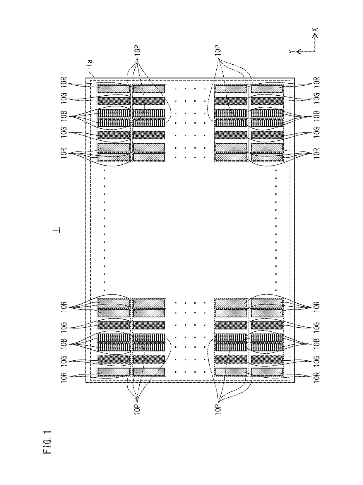
[0078]FIG. 1 illustrates an arrangement of organic light-emitting elements in a display panel 1.

[0079]The display panel 1 has a display region 1a in which an image is displayed. For example, red organic light-emitting elements 10R emitting red (R) light, green organic light-emitting elements 10G emitting green (G) light, and blue organic light-emitting elements 10B emitting blue (B) light are arrayed in the display region 1a in the X-axis direction and the Y-axis direction. The red organic light-emitting elements 10R, the green organic light-emitting elements 10G, and the blue organic light-emitting elements 10B (whenever it is unnecessary to distinguish the red organic light-emitting elements 10R, the green organic light-emitting elements 10G, and the blue organic light-emitting elements 10B from one another, the term “organic light-emitting elements 10” is hereinafter used) are disposed so as to correspond one-to-one with subpixels. For example, each...

embodiment 2

[0112]The following describes Embodiment 2, with reference to FIG. 9, FIG. 10, FIG. 11A, and FIG. 11B. A basic structure of a display panel 101 of Embodiment 2 illustrated in a cross-sectional view in FIG. 9 is substantially the same as Embodiment 1. Embodiment 2 differs from Embodiment 1 in that first column banks have a lower height than second column banks and third column banks, and that the first column banks, the second column banks, and the third column banks have the same width as one another. Note that components that appear in Embodiment 1 are indicated by using the same reference signs, and the explanation thereof is omitted as necessary.

1. Structure of Display Panel 101

[0113]Whenever it is unnecessary to distinguish first column banks 131, the second column banks 32, and the third column banks 33 in the display panel 101 from one another, the term “column banks 130” is hereinafter used. In the display panel 101, a width W131 of the first column banks 131, a width W32 of ...

embodiment 3

[0118]The following describes Embodiment 3, with reference to FIG. 12. A basic structure of a display panel 201 of Embodiment 3 illustrated in a cross-sectional view in FIG. 12 is substantially the same as Embodiment 1. Embodiment 3 differs from embodiment 1 in that first column banks, second column banks, and third column banks have the same height as one another, that the first column banks, the second column banks, and the third column banks have the same width as one another, and that the first column banks have lower liquid repellency than the second column banks and the third column banks. Note that components that appear in Embodiment 1 are indicated by using the same reference signs, and the explanation thereof is omitted as necessary.

1. Structure of Display Panel 201

[0119]Whenever it is unnecessary to distinguish first column banks 231, the second column banks 32, and the third column banks 33 in the display panel 201 from one another, the term “column banks 230” is hereina...


PUM


Abstract

A display panel including a substrate; first, second, and third lower electrodes; first and second column banks; first, second, and third organic light-emitting layers; and an upper electrode. When a first ink for forming the first organic light-emitting layer, a second ink for forming the second organic light-emitting layer, and a third ink for forming the third organic light-emitting layer are applied, ink-separating capability of the first column bank for separating the first ink and the second ink is lower than ink-separating capability of the second column bank for separating the second ink and the third ink, and ink-separating capability depends on: (i) a height of the first and second column banks, or (ii) liquid repellency of the first column bank against the first ink and the second ink and liquid repellency of the second column bank against the second ink and the third ink.

Description

[0001]This application is based on an application No. 2016-72150 filed in Japan, the contents of which are hereby incorporated by reference.BACKGROUND OF THE DISCLOSURE[0002](1) Technical Field[0003]The present disclosure relates to a display panel including an organic light-emitting element such as an organic light-emitting diode (OLED).[0004](2) Description of Related Art[0005]Display panels using organic light-emitting diodes are known. Such display panels include a substrate, lower electrodes disposed with gaps between each other in an X-axis direction and a Y-axis direction, organic light-emitting layers disposed on the lower electrodes, and an upper electrode that are disposed in this order, and may further include, as necessary, layers such as a hole injection layer, a hole transport layer, an electron injection layer, an electron transport layer, and a sealing layer. In such display panels, column banks extending in the Y-axis direction may be disposed in gaps between lower ...

Claims


Application Information

Patent Timeline
Patent Type & Authority Patents(United States)
IPC IPC(8): H01L27/32H01L51/00H01L51/50
CPCH01L27/3246H01L27/3211H01L51/0005H01L51/5092H01L51/5072H01L51/5088H01L51/5056H10K59/35H10K59/122H10K71/135H10K71/191H10K50/15H10K50/16H10K50/17H10K50/171
Inventor TAKATA, MASAKAZU
Owner JOLED INC
Why Eureka
Try Eureka