Image processing method and computer program

a digital image and computer program technology, applied in the field of digital image processing method and computer program, can solve the problems of not being able to comprehensively solve the problem of mass shadows that are not necessarily so simple as to have various shapes, the interpretation system is nowhere near a practical level, and the physician with sufficient experience may hesitate to make a decision

Inactive Publication Date: 2014-12-16
JAPAN IMAGE ANALYSIS ASSOC
View PDF17 Cites 0 Cited by
  • Summary
  • Abstract
  • Description
  • Claims
  • Application Information

AI Technical Summary

Benefits of technology

[0013]In the present invention, in step (Sa3), since a mean value of an amplitude value β of a gradient is calculated by summing degrees of inclination between a pixel of interest and neighboring pixels thereof over a whole circumference around the pixel of interest and dividing the sum by the number of pixels within a target region, an angular component of the gradient is cancelled out and a difference image not including angular information and solely including an amplitude value is generated. Furthermore, since an amplitude value is further enhanced by multiplying by a contrast intensity m, the greater the difference in image signals between a pixel of interest and a neighboring pixel, the stronger the display.
[0022]The image processing method according to the present invention enables a characteristic of an input image to be extracted or highlighted and displayed. In addition, by removing an extraction result using known threshold processing, a pattern having a specific characteristic can be removed from the input image.

Problems solved by technology

However, in reality, mass shadows have various shapes and are not necessarily so simple as to be comprehensively solved by a model such as that described above.
However, at present, the interpretation system is nowhere near a practical level from a comprehensive perspective and is considered to be merely a supplementary tool for diagnostics.
In other words, with mammography interpretation, there are many cases where even a physician with sufficient experience may hesitate to make a decision.
While the Japan Radiological Society has formulated a guideline in an attempt to standardize an interpretation method or the like of mammography diagnostics for the purpose of detecting breast cancer, this itself is indicative of how difficult it is to determine a mass.
In particular, with respect to the discovery of a mass in mammography diagnostics of mammary glands, it is extremely difficult to distinguish a simple overlapping of mammary glands from a true mass.

Method used


Image

  • Image processing method and computer program
  • Image processing method and computer program
  • Image processing method and computer program

Examples


first embodiment

Extraction Processing of a Characteristic Point Using an Amplitude Value of a Differential Image

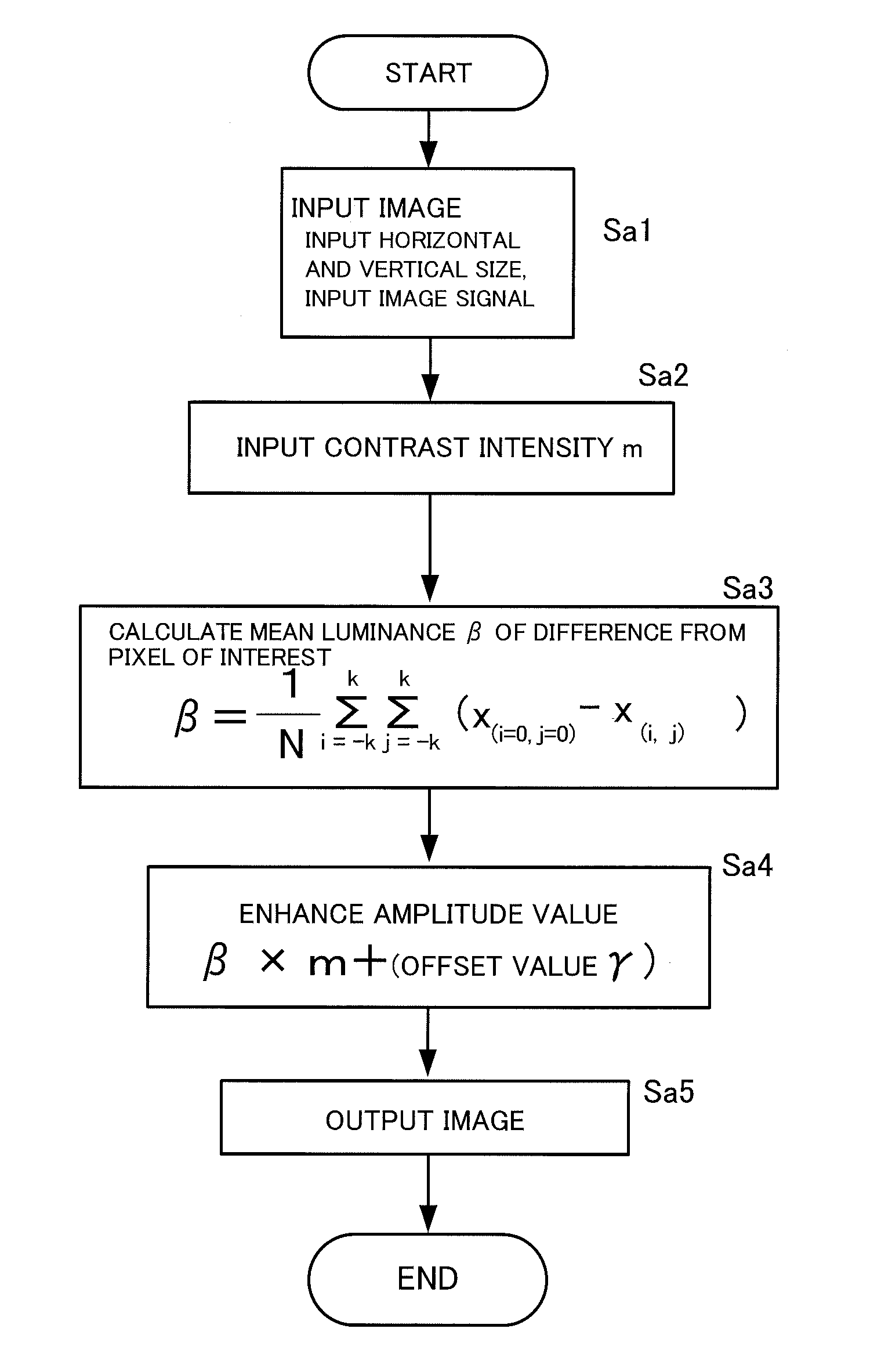
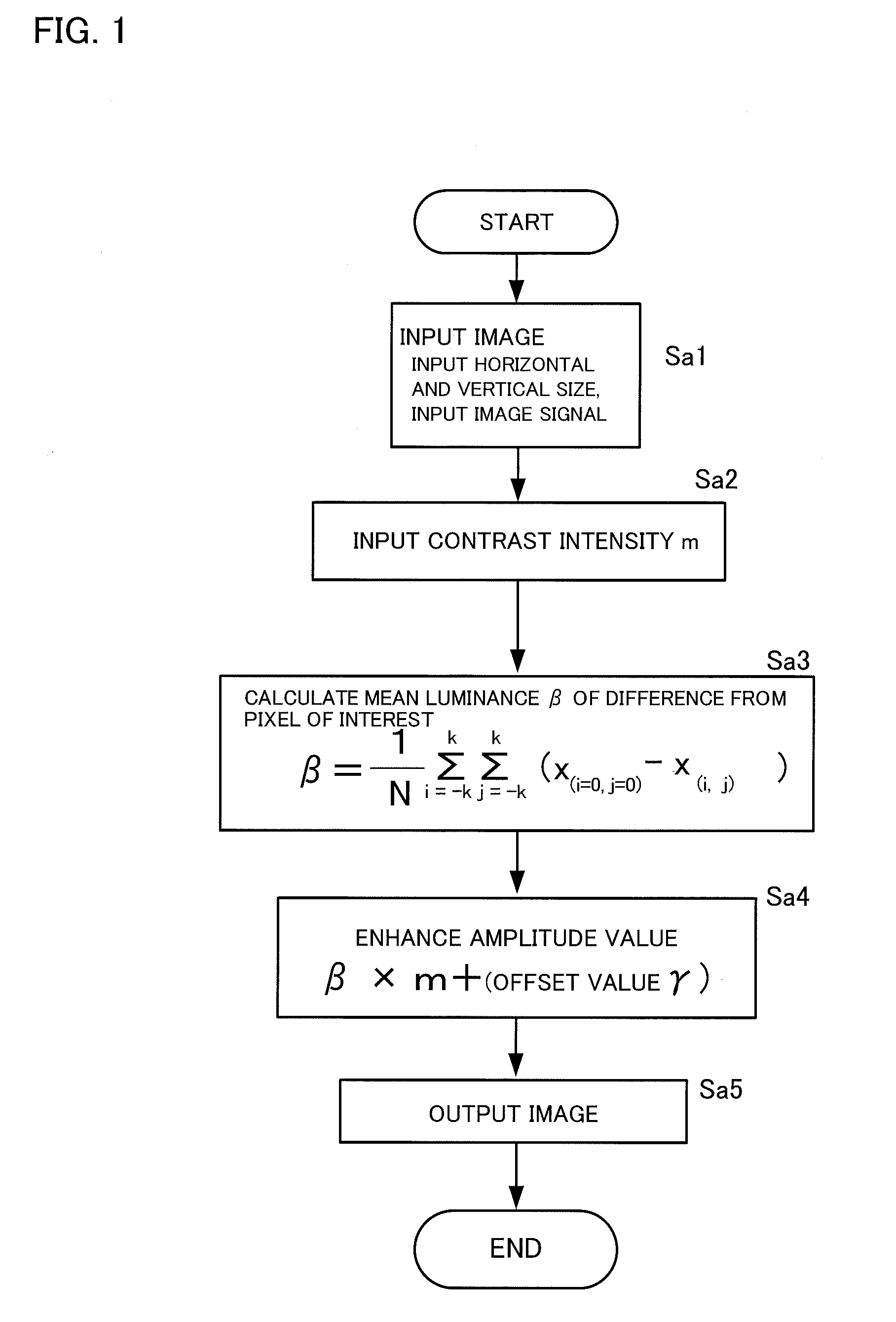
[0035]FIG. 1 is a diagram illustrating a procedure of an image processing method according to a first embodiment of the present invention.

[0036]Following a step (Sa1) for inputting data of an input image into a computer, a step (Sa2) for inputting an arbitrarily defined constant m as a contrast intensity is executed. The constant m is a positive constant for defining an intensity of contrast to be assigned to an output image.

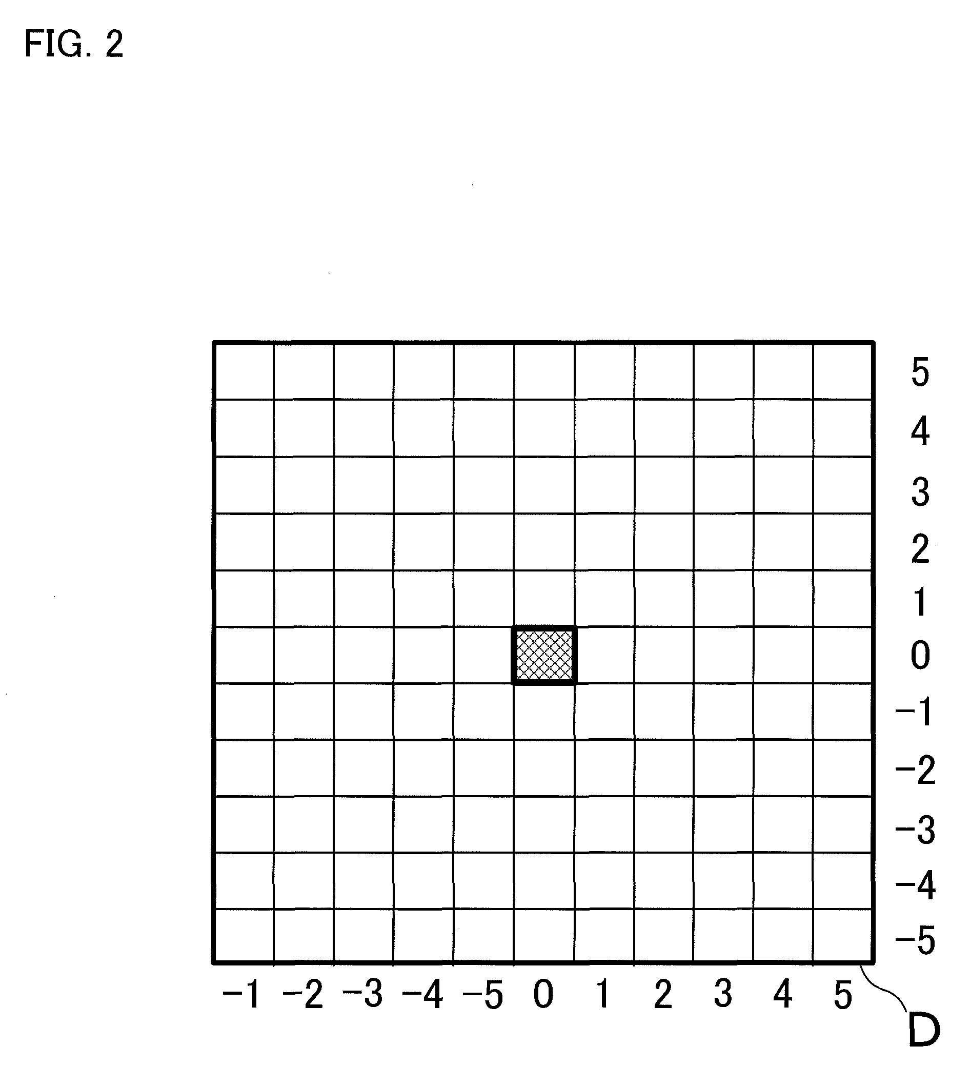
[0037]FIG. 2 illustrates a target region D demarcating a closed region (x, y) made up of a plurality of pixels in the input image. In this example, five neighboring pixels of a center (pixel of interest) of the region are set as the target region. If a pixel of interest x (i=0, j=0), then an amplitude value β is defined as expressed in Expression 1.

[0038]β=1N⁢∑i=-55⁢∑j=-55⁢(χ(i=0,j=0)-χ(i,j))⁢⁢(N⁢:⁢⁢number⁢⁢of⁢⁢pixels)[Expression⁢⁢1]

[0039]Generally, an amplitude value...

second embodiment

Stereoscopic Visualization Processing Using a Gradient Vector

[0048]FIG. 4 is a diagram illustrating a procedure of an image processing method according to a second embodiment of the present invention. Generally, a “gradient vector” is defined as a vector quantity for expressing a differential image having angular information. In the following description, it is assumed that an image signal represents luminance and a value of the image signal represents a luminance value. In addition, for convenience of description, a luminance value is to be expressed in 8 bits or, in other words, is to assume a value ranging from 0 to 255.

[0049]FIG. 5(a) illustrates a target region (mask) C provided in the input image. As an example, the target region C is set to a region of neighboring pixels that are one pixel away from a central pixel. In this case, a luminance value of a central pixel of the target region C is denoted by α and neighboring luminance values of the central pixel are respectively d...

third embodiment

Edge Detection Processing Using a Laplacian Filter

[0067]In this embodiment, a method for performing edge detection by adapting a Laplacian filter to an output image of a conventionally-known iris filter will be described. An object of edge detection is to extract a characteristic portion of an image signal of each pixel included in an input image using a computer and perform so-called “marking” in which the characteristic portion is enclosed by a closed line.

[0068]FIG. 8 is a diagram illustrating a procedure of an image processing method according to a third embodiment of the present invention. Steps (Sc2) to (Sc3) represent a known algorithm referred to as an “iris filter” for obtaining a degree of concentration of an image signal such as a luminance value.

[0069]First, data of an input image is inputted into a computer, a closed region (x, y) made up of a plurality of pixels in the input image is demarcated as a target region C, a gradient vector is obtained from coordinates of a p...


PUM


Abstract

To assign angle-dependent information to an input image in order to highlight and display one-dimensional patterns. First, data of an input image is inputted to a computer (Sa1). An arbitrarily defined constant m is then inputted as a contrast intensity (Sa2). Next, a closed region (x, y) made up of a plurality of pixels in the input image is demarcated as a target region D, degrees of inclination between respective two pixels, namely, a pixel of interest in the target region D and arbitrarily defined neighboring pixels thereof, are summed over a whole circumference around the pixel of interest, and the sum is divided by the number of pixels within the target region to calculate a mean value thereof (Sa3). Furthermore, an amplitude value β of a gradient obtained in step (Sa3) is multiplied by the contrast intensity m (where m is a positive constant) inputted in step (Sa2) and an arbitrarily defined offset value γ is added to the obtained value (Sa4) to obtain a final output image (Sa5).

Description

BACKGROUND OF THE INVENTION[0001]1. Field of the Invention[0002]The present invention relates to a digital image processing method and a computer program for extracting a particular portion included in a digital image to be highlighted and displayed or, conversely, to be removed.[0003]2. Description of the Related Art[0004]In a digital image, when comparing a pixel of interest and a neighboring pixel, a vector expressing information related to a change in digitalized image signals (for example, luminance values) of both pixels is generally referred to as a “differential image” or a “gradient image” (in the present specification, the term “differential image” will be uniformly used). A differential image represents a “gradient vector” calculated when comparing two points (two pixels), namely, a pixel of interest and an arbitrarily defined neighboring pixel thereof from respective changes in coordinates and digital values. An “iris filter” is known as an image processing algorithm uti...

Claims


Application Information

Patent Timeline
Patent Type & Authority Patents(United States)
IPC IPC(8): G06K9/00A61B6/00G06K9/40G06T5/00G06T7/00
CPCG06T5/008A61B6/5217G06T7/0081A61B6/502G06T2207/20012G06T7/11G16H50/30
Inventor TERADA, TOSHIHIKOYAMAUCHI, HIRONORI
Owner JAPAN IMAGE ANALYSIS ASSOC
Why Eureka
Try Eureka