
Formed body manufacturing method and formed body manufacturing apparatus

a manufacturing method and technology of a formed body, applied in the direction of coatings, molten spray coatings, metallic material coating processes, etc., can solve the problems of achieve the effect of forming efficient heat dissipation coatings and not reducing the quality of the formed body

Active Publication Date: 2019-01-01
TOYOTA JIDOSHA KK
View PDF9 Cites 0 Cited by
  • Summary
  • Abstract
  • Description
  • Claims
  • Application Information

AI Technical Summary

Benefits of technology

The patent describes a method and apparatus for making a formed body with a heat dissipation coating on its surface. By using a resin-containing coating material that can be blown to the surface of the formed body at a high temperature, the heat dissipation coating can be efficiently formed without needing to heat the formed body. This method and apparatus can help to improve the quality of the formed body while also promoting efficient production.

Problems solved by technology

However, in this method, in a case where the coating material is blown to the molten metal lifted up from the molten metal surface but not solidifying yet, a sectional shape of the molten metal not solidifying yet deforms due to a blowing pressure, which might decrease quality of the formed body.

Method used


Image

  • Formed body manufacturing method and formed body manufacturing apparatus
  • Formed body manufacturing method and formed body manufacturing apparatus
  • Formed body manufacturing method and formed body manufacturing apparatus

Examples


embodiment 1

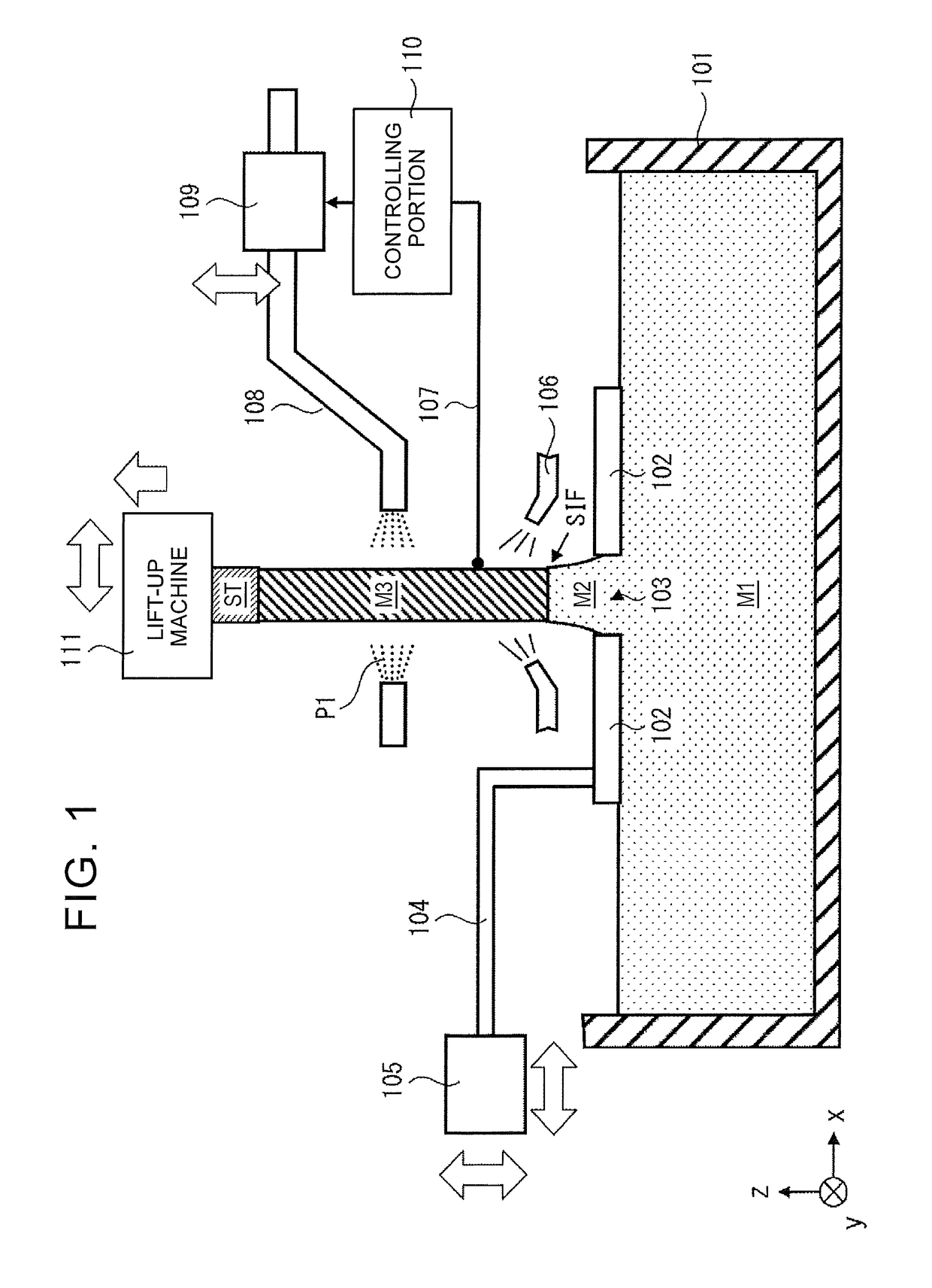
[0025]First described is a formed body manufacturing apparatus according to Embodiment 1, with reference to FIG. 1. FIG. 1 is a sectional view schematically illustrating the formed body manufacturing apparatus according to Embodiment 1. As illustrated in FIG. 1, the formed body manufacturing apparatus according to Embodiment 1 includes a molten metal holding furnace (holding furnace) 101, a shape defining member 102, a support rod 104, an actuator 105, a coolant gas nozzle 106, a thermoelectric couple 107, a coating material spray nozzle 108, an actuator 109, a controlling portion 110, and a lift-up machine 111. Note that an xyz right coordinate system is illustrated in FIG. 1 for convenience of description of a positional relationship between constituents. An xy plane in FIG. 1 constitutes a horizontal plane, and a z-axis direction is a vertical direction. More specifically, a positive direction of the z axis is an upper side in the vertical direction.

[0026]The molten metal holding...

embodiment 2

[0050]FIG. 5 is a flowchart illustrating a formed body manufacturing method according to Embodiment 2. The formed body manufacturing method according to Embodiment 2 is different from the formed body manufacturing method according to Embodiment 1 in how to adjust the coating material spray nozzle 108 based on the measurement result by the thermoelectric couple 107.

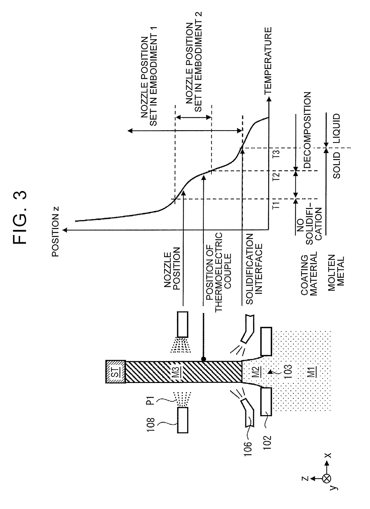
[0051]As illustrated in FIG. 5, when it is determined that a surface temperature of a formed body M3 to which a heat dissipation coating material P1 is blown is not less than a temperature T2 (see FIG. 3) at which the heat dissipation coating material P1 decomposes (NO in step S206), a controlling portion 110 moves a coating material spray nozzle 108 upward (step S207). Further, even in a case where the surface temperature of the formed body M3 to which the heat dissipation coating material P1 is blown is less than the temperature T2 at which the heat dissipation coating material P1 decomposes (YES in step S206), if it is ...


PUM

PropertyMeasurementUnit
distanceaaaaaaaaaa
shapeaaaaaaaaaa
surface temperatureaaaaaaaaaa

Abstract

In a formed body manufacturing method, molten metal is led out from a molten metal surface of the molten metal held in a holding furnace and is passed through a shape defining member configured to define a sectional shape of the formed body, and the formed body manufacturing method includes: measuring a surface temperature of the formed body formed such that retained molten metal that has passed through the shape defining member solidifies; adjusting a height of a coating material spray nozzle based on a result of the measurement of the surface temperature of the formed body so that the surface temperature of the formed body to which the heat dissipation coating material is blown becomes a solidifying point of the molten metal or less; and spraying the heat dissipation coating material to a surface of the formed body from the coating material spray nozzle.

Description

INCORPORATION BY REFERENCE[0001]The disclosure of Japanese Patent Application No. 2016-218099 filed on Nov. 8, 2016 including the specification, drawings and abstract is incorporated herein by reference in its entirety.BACKGROUND1. Technical Field[0002]The present disclosure relates to a formed body manufacturing method and a formed body manufacturing apparatus.2. Description of Related Art[0003]Japanese Patent No. 5373728 discloses a device for manufacturing a metal formed body. In the device disclosed in Japanese Patent No. 5373728, when a starter is immersed into a surface of molten metal (that is, a molten metal surface) and then the starter is lifted up, the molten metal is also led out following the starter due to a surface film and a surface tension of the molten metal. Here, formed bodies having a desired sectional shape can be continuously formed such that the molten metal is led out via a shape defining member placed on the molten metal surface, and then, the molten metal ...

Claims


Application Information

Patent Timeline
Patent Type & Authority Patents(United States)
IPC IPC(8): B22D11/01B22D27/04B22D23/00B22D11/14B22D11/12B22D11/124
CPCB22D11/01B22D11/145B22D27/045B22D23/003B22D11/1246B22D11/1213B22D11/22C23C2/04C23C4/00
Inventor EGAWA, YUTA
Owner TOYOTA JIDOSHA KK
Learn More