Substrate treating apparatus

a technology for treating apparatus and substrates, which is applied in the direction of photomechanical equipment, instruments, and photosensitive material processing, etc., can solve the problems of difficult to supply an appropriate quantity of gas to both and the timing of substrate treatment carried out by the first treating unit and the timing of substrate treatment carried out by the second treating unit is not necessarily the same, so as to improve the treatment quality of the first treating unit and the second treating unit. , the effect of improving

Active Publication Date: 2019-01-01
DAINIPPON SCREEN MTG CO LTD
View PDF27 Cites 11 Cited by
  • Summary
  • Abstract
  • Description
  • Claims
  • Application Information

AI Technical Summary

Benefits of technology

[0011]This invention has been made having regard to the state of the art noted above, and its object is to provide a substrate treating apparatus which can improve the treatment quality of each of a plurality of treating units.
[0055]According to the invention in paragraph (9) above, the treatment quality of each solution treating unit can be improved further conveniently.

Problems solved by technology

However, the timing of substrate treatment carried out by the first treating unit and the timing of substrate treatment carried out by the second treating unit are not necessarily the same.
When the first period and the second period are staggered, it is difficult to supply an appropriate quantity of gas to both the first treating unit and second treating unit in a timely way.
It is therefore difficult to improve the treatment quality of each of the first treating unit and the second treating unit.
Similarly, the rate of gas exhaust from the first treating unit and the rate of gas exhaust from the second treating unit cannot be changed individually.
It is therefore difficult to improve the treatment quality of each of the first treating unit and the second treating unit.

Method used


Image

  • Substrate treating apparatus
  • Substrate treating apparatus
  • Substrate treating apparatus

Examples


Embodiment Construction

[0074]An embodiment of this invention will be described hereinafter with reference to the drawings.

[0075]

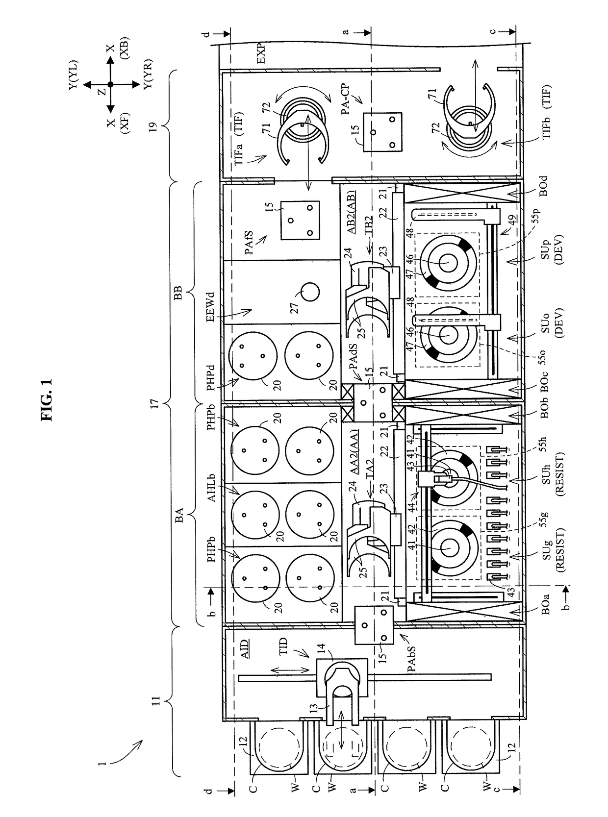
[0076]FIG. 1 is a plan view of a substrate treating apparatus according to this invention. A substrate treating apparatus 1 treats wafers W. The “wafers W” here means semiconductor wafers, glass substrates for photomasks, glass substrates for liquid crystal displays, substrates for plasma displays, substrates for optical disks, substrates for magnetic disks, substrates for magneto-optical disks and so on (hereinafter called simply wafers).

[0077]The substrate treating apparatus 1 includes an indexer section 11, a treating section 17 and an interface section 19. The indexer section 11 is connected to the treating section 17. The indexer section 11 feeds the wafers W to the treating section 17. The treating section 17 performs solution treatment in which treating solutions are supplied to the wafers W, for example. The interface section 19 is connected to the treating section 17. Fu...


PUM

PropertyMeasurementUnit
solutionaaaaaaaaaa
shapeaaaaaaaaaa
sizeaaaaaaaaaa

Abstract

A substrate treating apparatus includes a plurality of solution treating units for performing solution treatment of substrates, and a plurality of individual gas supply devices provided to correspond individually to the solution treating units, each for supplying gas at a variable rate only to one of the solution treating units. The solution treating units perform the solution treatment by supplying treating solutions to the substrates. The individual gas supply devices supply gas only to the solution treating units corresponding thereto. The individual gas supply devices supply the gas at adjustable rates to the solution treating units. The rate of gas supply to the solution treating units can therefore be varied for each solution treating unit.

Description

CROSS-REFERENCE TO RELATED APPLICATIONS[0001]This application claims priority to Japanese Patent Application No. 2015-223003 filed Nov. 13, 2015, the disclosure of which is hereby incorporated herein by reference in its entirety for all purposes.BACKGROUND OF THE INVENTION[0002](1) Field of the Invention[0003]This invention relates to a substrate treating apparatus for treating semiconductor wafers, glass substrates for photomasks, glass substrates for liquid crystal displays, substrates for optical disks and so on (hereinafter called simply substrates).[0004](2) Description of the Related Art[0005]Conventionally, this type of apparatus includes an apparatus having a treating section, a gas supply device and a gas exhaust device. The treating section has a first treating unit and a second treating unit arranged horizontally. The gas supply device supplies gas to the first treating unit and second treating unit together. The gas exhaust device exhausts gas from the first treating uni...

Claims


Application Information

Patent Timeline
Patent Type & Authority Patents(United States)
IPC IPC(8): B05C13/00H01L21/67B05D1/00G03F7/16B05C5/02G03F7/30B05C15/00
CPCH01L21/67178B05C5/0208B05D1/005G03F7/3092H01L21/67017G03F7/162B05C15/00H01L21/00H01L21/6715H01L21/67173H01L21/6719H01L21/67253H01L21/67742
Inventor MAEDA, MASAFUMI
Owner DAINIPPON SCREEN MTG CO LTD
Why Eureka
Try Eureka