Decompression processing apparatus

a processing apparatus and decompression technology, applied in the direction of photomechanical apparatus, instruments, printers, etc., can solve the problem of insufficient sticking force of the wafer, and achieve the effect of suppressing the effect of moisture, preventing condensation from forming, and reducing the decompression tim

Active Publication Date: 2019-01-08
DISCO CORP
View PDF2 Cites 1 Cited by
  • Summary
  • Abstract
  • Description
  • Claims
  • Application Information

AI Technical Summary

Benefits of technology

[0004]It is accordingly an object of the present invention to provide a decompression processing apparatus that can prevent the occurrence of condensation and which can shorten decompression time.
[0006]According to this constitution, the inert gas generates a positive pressure within the decompression chamber, and therefore the inert gas is discharged from the inside of the decompression chamber to the outside via the carrying-in-and-out opening when the opening and closing door is opened. At this time, the inert gas continues to be supplied to the inside of the decompression chamber, and therefore the inert gas continues to be discharged from the carrying-in-and-out opening. Hence, the outside air does not enter the inside of the decompression chamber from the carrying-in-and-out opening against the flow of the inert gas, and the inert gas maintains the inside of the decompression chamber in a dry state. Because humidity within the decompression chamber is not raised by the outside air when the wafer is carried into and carried out of the decompression chamber, condensation can be prevented from forming on the holding table. In addition, the decompression time can be shortened by suppressing the effect of moisture, which hinders decompression.
[0007]According to the present invention, the opening and closing door is opened while the inert gas continues to be supplied to the inside of the decompression chamber. Thus, the outside air does not enter the inside of the decompression chamber from the carrying-in-and-out opening, and the inert gas maintains the inside of the decompression chamber in a dry state. Hence, the occurrence of condensation can be prevented, and the decompression time can be shortened.

Problems solved by technology

When moisture included in the outside air is cooled by the cooled electrostatic chuck, condensation forms on the surface of the electrostatic chuck, so that a sufficient sticking force for the wafer is not obtained.

Method used


Image

  • Decompression processing apparatus
  • Decompression processing apparatus
  • Decompression processing apparatus

Examples


Embodiment Construction

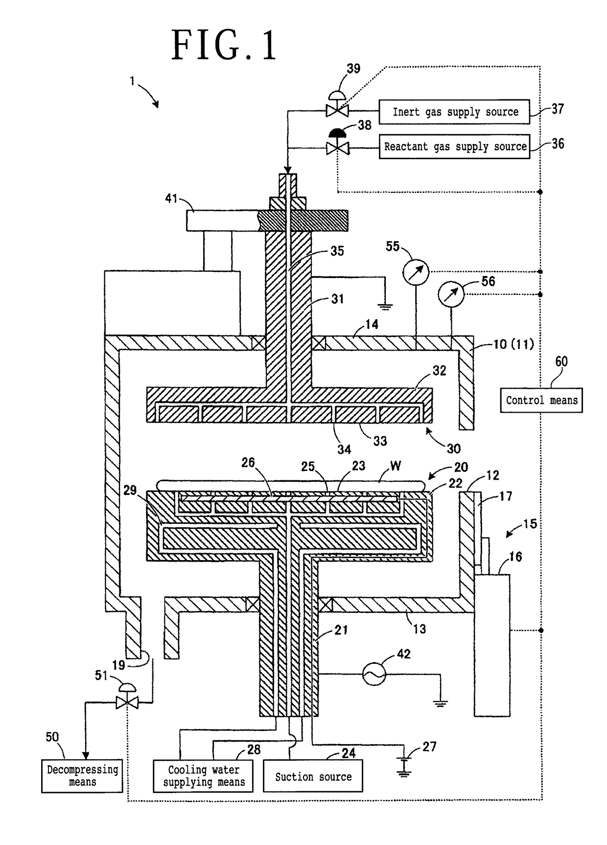
[0012]An etching apparatus as a decompression processing apparatus will hereinafter be described with reference to the accompanying drawings. FIG. 1 is a general schematic diagram of an etching apparatus according to the present embodiment. Incidentally, while description will be made by illustrating a plasma etching apparatus for capacitive coupled plasma (CCP) as a decompression processing apparatus in the present embodiment, the decompression processing apparatus may be various other kinds of plasma etching apparatuses such as a plasma etching apparatus for inductive coupled plasma (ICP) and the like. In addition, it suffices for the decompression processing apparatus to be an apparatus processing a wafer in a decompressed state. The decompression processing apparatus may be, for example, a film forming apparatus that grows a film on the top surface of a wafer.

[0013]As depicted in FIG. 1, an etching apparatus 1 is configured to convert a reactant gas (etching gas) into plasma wit...


PUM

PropertyMeasurementUnit
temperatureaaaaaaaaaa
humidityaaaaaaaaaa

Abstract

Disclosed herein is a decompression processing apparatus for processing a wafer in a decompressed state including a chamber having a decompressing unit configured to decompress the inside of the chamber, an opening and closing door configured to open and close a carrying-in-and-out opening for carrying the wafer into and out of the chamber, and an inert gas supply source configured to supply an inert gas to the inside of the chamber. The inside of the chamber is maintained in a dry state by continuing to supply the inert gas in a state in which the opening and closing door is opened.

Description

BACKGROUND OF THE INVENTIONField of the Invention[0001]The present invention relates to a decompression processing apparatus that decompresses the inside of a decompression chamber when processing a wafer.Description of the Related Art[0002]A grinding trace remains on a ground surface of a wafer after being ground by a grinding apparatus. This grinding trace causes a decrease in transverse rupture strength of the wafer. Accordingly, an apparatus has been proposed which removes the grinding trace from the ground surface of the wafer by plasma etching (see Japanese Patent Laid-Open No. 2001-358097, for example). In a plasma etching apparatus, the wafer is carried into a chamber (decompression chamber) from the outside via an opening and closing door, and an etching gas is supplied to the inside of the chamber in a state in which the inside of the chamber is decompressed. Then, the grinding trace is removed from the ground surface by making the etching gas converted into plasma react o...

Claims


Application Information

Patent Timeline
Patent Type & Authority Patents(United States)
IPC IPC(8): G03B27/42G03F7/20H01L21/3065H01L21/683H01L21/67
CPCG03F7/70866G03F7/70708H01L21/6831H01L21/67109H01L21/3065H01L21/67069H01L21/67017H01L21/67772H01L21/683
Inventor IIDA, HIDEKAZU
Owner DISCO CORP
Why Eureka
Try Eureka