Valve seat puller

a valve seat and puller technology, applied in the direction of pump components, liquid fuel engine components, liquid fuel engines, etc., can solve the problems of difficulty in removing the seat after, lost money during the down time, complex and expensive, etc., and achieve the effect of convenient use and time-saving

Active Publication Date: 2019-01-15
HUNTER JACOB
View PDF8 Cites 2 Cited by
  • Summary
  • Abstract
  • Description
  • Claims
  • Application Information

AI Technical Summary

Benefits of technology

[0013]In view of the foregoing disadvantages inherent in the known types of pullers now present in the prior art, the present invention provides a new and improved apparatus and system, which is easier to utilize and more time efficient. As such, the general purpose of the present invention, which will be described subsequently in greater detail, is to provide a new and improved seat puller apparatus and system for replacing seats, which has all the advantages of the prior art devices and none or fewer of the disadvantages.
[0018]Therefore, it is an object of the present invention to provide a new and improved apparatus, system and method for removing and or pulling seats, pump liners, and so forth, which may be easily and efficiently utilized.
[0019]It is a further object of the present invention to provide a new and improved apparatus, system and method for removing seats, pump liners, and so forth, which is of a durable and reliable construction and may be utilized with multiple types of applications in the oil and gas field as well as other applications.
[0020]An even further object of the present invention is to provide a new and improved apparatus, system and method for removing seats, pump liners and so forth, which is generally susceptible to a low cost of manufacture with regard to both materials and labor, and which accordingly is then susceptible to low prices of sale to the consuming industry, thereby making such tool economically available to those in the field.
[0023]Yet another object of the present invention is to provide a new and improved apparatus, system and method for removing seats, pump liners, and so forth that may allow for one individual to operate, may be operated with no one having to reach inside a pump head, and generally reduces the risk of injury.
[0024]Still another object of the present invention is to provide a new and improved apparatus, system and method for removing seats, pump liners, and so forth, which increases the speed of the replacement operation regarding changing out of associated parts.

Problems solved by technology

Due to the nature of seats in general, it is often extremely difficult to remove the seat after it is installed.
There are many prior art devices for pulling pump valve seats and liners, but most of them are complex and expensive.
If a valve seat puller is complex, it consumes time in the removal of the valve seat, which translates into money lost during the down time.
Over time with the opening and closing of the valves against seat creates wear causing the valves not to seal.
These types of pullers fail regularly in that they will not withstand very high pulling pressures.
This naturally exposes the head of the pump to be “nicked” or cut into with the torch that can cause the head to have to be removed and taken to be repaired.
This prior art device has several inherent problems due to the configuration of the individual J-shaped hooks and need for the hooks to pivot by a mechanical means.
Needless to say, any obstruction in the pivot movement would prevent the J-shaped hook from rotating out for extending and thus would not allow for the hook to catch the valve seat.
Also of note, rust would frequently inhibit the pivot movement requiring cleaning and lubricating of the part to keep it from binding.
Furthermore, sometimes the hook would be stuck in the extended position because the pivot problem.
This would mean that the J-shaped hook would not pass through the valve seat opening and often would cause further damage when hitting the valve seat.
It is not uncommon for the stuck out J-shaped hook to further push down the seat, damage, it and so forth making it even more difficult to remove.
Current valve seats are typically seated in a tighter fashion making the torque required to rotational lift extremely high which leads to failures, stripping of threads, and damage to motors needed to provide the rotational movement.
Present day drilling operations are extremely expensive, and an effort to increase the overall efficiency of the drilling operation while minimizing expense requires the essentially continuous operation of the drilling rig.

Method used


Image

  • Valve seat puller
  • Valve seat puller
  • Valve seat puller

Examples


Embodiment Construction

[0056]Referring to the illustrations, drawings, and pictures, reference character 10 generally designates a new and improved puller device, assembly, system and method of using same constructed in accordance with the present invention. Invention 10 is generally used in oil and gas well operations but may be utilized in other applications. The current invention should not be considered limited to just removing seat, valve seat, pump liners, and so forth.

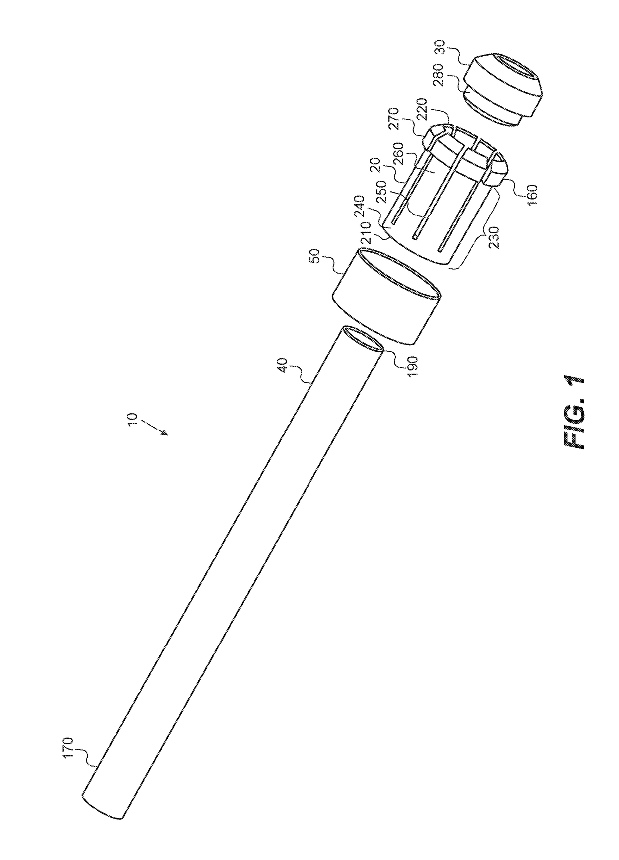
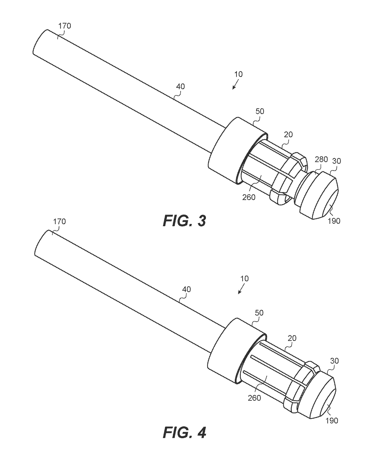
[0057]Now referring to the illustrations and more in particular to FIG. 1, invention 10 may include spring catch 20, bottom nose 30, puller shaft 40, and sleeve 50 generally positioned axially as depicted in the illustrations as will be discussed further below.

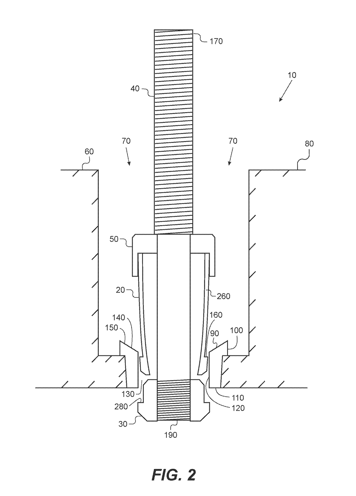
[0058]Again referring to the drawings in general and more specifically to FIG. 2, invention 10 may generally be utilized with pump assembly 60. A portion of the invention 10 is generally depicted being inserted into hole or opening 70 of pump or pump head 80 for engaging stuck v...


PUM


Abstract

The present invention provides an apparatus, system and method for replacing seats utilizing J-shaped hooks on a puller shaft that may be compressed to pass through the seat and expand back to engage the seat from below for pulling upward and removal.

Description

CROSS-REFERENCE TO RELATED APPLICATIONS[0001]The present application is a continuation-in-part of U.S. patent application Ser. No. 14 / 267,035, filed on May 1, 2014, currently pending, which claims priority from U.S. Provisional Patent Application Ser. No. 61 / 854,852, filed on May 2, 2013. The present application also claims priority from U.S. Provisional Patent Application Ser. No. 62 / 168,413 filed on May 29, 2015. Each of the applications listed above is hereby expressly incorporated herein by reference in their entirety.BACKGROUND OF THE INVENTION1. Field of the Invention[0002]In general, the present invention relates to an apparatus and system for removing seats. More particularly, the present invention provides an improved puller that utilizes spring loaded J-shaped hooks for removing various seats, valve seats, pump liners and so forth from oilfield fracturing pumps, mud pumps, nitrogen pumps, and other equipment found in the oil and gas industry as well as other equipment util...

Claims


Application Information

Patent Timeline
Patent Type & Authority Patents(United States)
IPC IPC(8): B25B27/02F04B53/10
CPCB25B27/02F04B53/1087B25B27/06B25B27/062B25B27/064B25B27/24
Inventor HUNTER, JACOB
Owner HUNTER JACOB
Why Eureka
Try Eureka