Eureka AIR delivers breakthrough ideas for toughest innovation challenges, trusted by R&D personnel around the world.

Seal, method for producing a seal and turbomachine

a technology of turbomachines and seals, applied in the direction of machines/engines, additive manufacturing processes, machines/engines, etc., can solve the problems of poor run-in behavior and seals produced by generative or additive methods, and achieve the effects of reducing energy input, simple generative construction of seals, and improving run-in performan

Active Publication Date: 2019-01-22
MTU AERO ENGINES GMBH
View PDF22 Cites 2 Cited by
  • Summary
  • Abstract
  • Description
  • Claims
  • Application Information

AI Technical Summary

Benefits of technology

The present invention provides a seal for sealing gaps between stationary and moving components of a turbomachine, which has improved run-in performance. The seal is produced layer-by-layer by a free-forming method, where weak regions are formed in the edge zone of the sealing segment to reduce thermal and mechanical stress during run-in. The seal can be formed as a honeycomb seal with different honeycomb geometries. The invention also provides a method for producing the seal and a turbomachine with improved efficiency based on the seal.

Problems solved by technology

As a disadvantage of the known seals produced by means of generative or additive methods, in particular honeycomb seals, is the circumstance, however, that they must be built up with a minimum wall thickness that is pre-defined by the method parameters.
This minimum wall thickness, however, is thicker than the conventionally produced honeycomb seals made of sheet metal, which leads to a poorer run-in behavior.

Method used


Image

  • Seal, method for producing a seal and turbomachine
  • Seal, method for producing a seal and turbomachine
  • Seal, method for producing a seal and turbomachine

Examples


Embodiment Construction

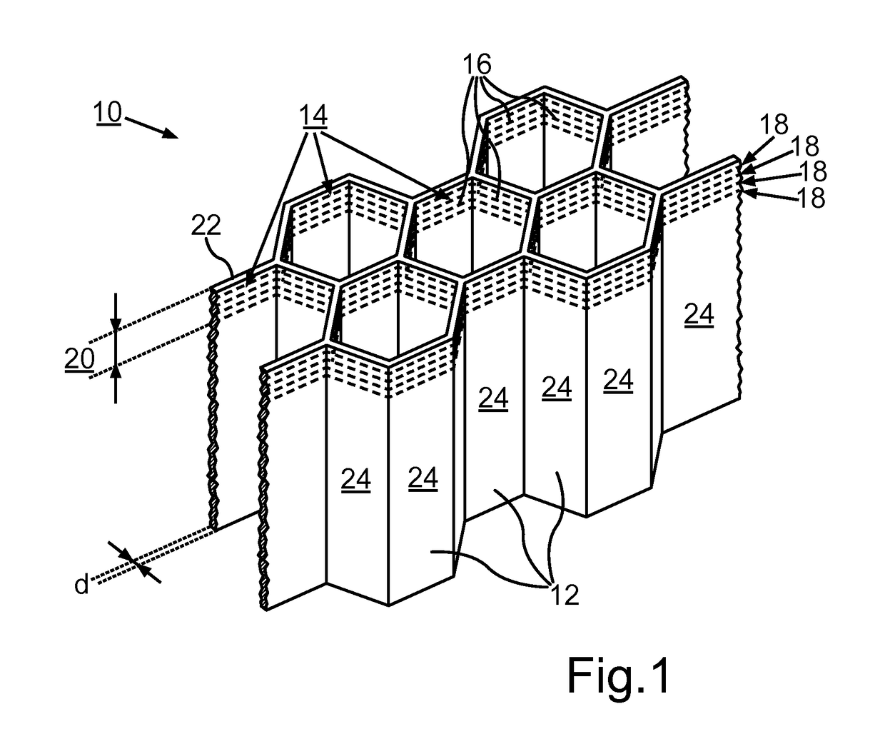
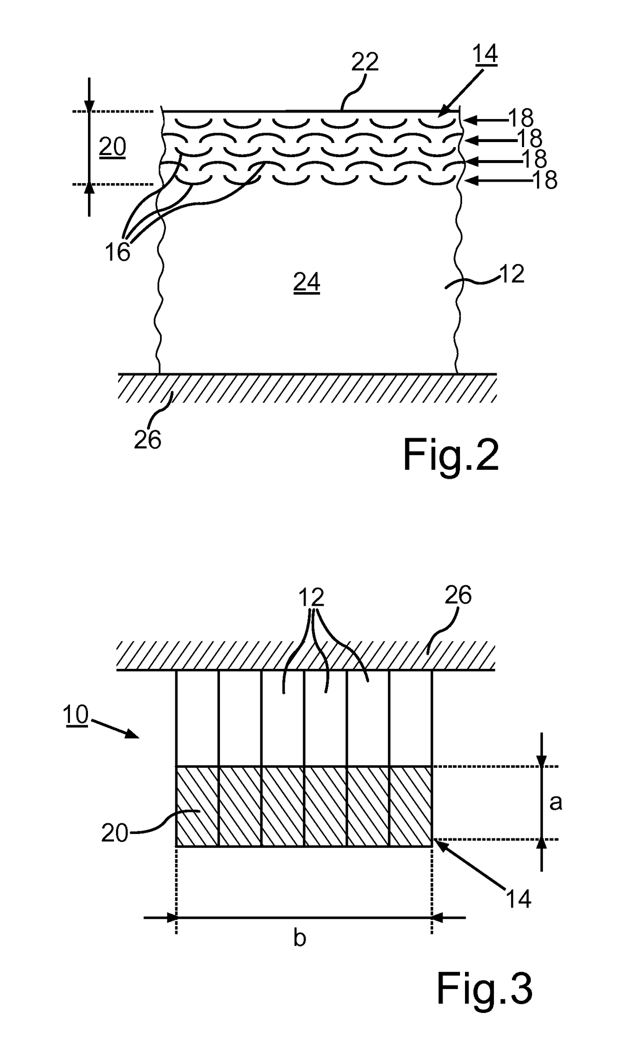
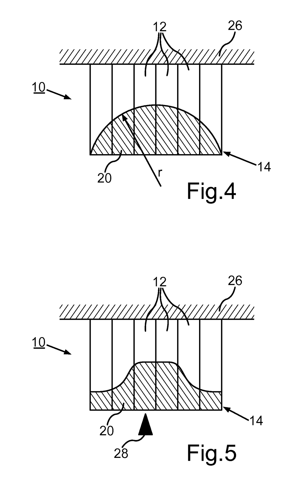
[0023]FIG. 1 shows a schematic representation of a seal 10 for sealing a gap between a stationary component and a moving component, in particular for sealing a radial gap between a rotor and a stator of a turbomachine, The seal 10 comprises a plurality of sealing segments 12, each of which has an edge zone 14 facing the gap to be sealed (not shown). In the embodiment example shown, the seal 10 is shown as a so-called honeycomb seal. The sealing segments 12 in this case form honeycomb segments. These honeycomb segments are shown with a hexagonal honeycomb geometry in the embodiment example. It is also possible, however, that the segments have a different honeycomb geometry. The seal 10 is produced layer-by-layer by means of a free-forming method, in particular a generative or additive method.

[0024]The edge zone 14 also comprises the so-called run-in region of the seal 10 or of the individual sealing segments 12. It can be recognized that a plurality of pre-defined weak regions 16 are...


PUM

PropertyMeasurementUnit
thicknessaaaaaaaaaa
radial dimensionaaaaaaaaaa
sizeaaaaaaaaaa

Abstract

The invention relates to a seal (10) for sealing a gap between a stationary component and a moving component, in particular for sealing a radial gap between a rotor and a stator of a turbomachine, comprising at least one sealing segment (12) with an edge zone (14) facing the gap, whereby the seal (10) is produced layer-by-layer by a free-forming method, in particular a generative or additive method. A plurality of pre-defined weak regions (16) is formed in the edge zone (14) of the sealing segment (12). In addition, the invention relates to a method for producing a seal (10) as well as a turbomachine.

Description

BACKGROUND OF THE INVENTION[0001]The studies that have led to this invention were supported by the Grant Agreement No. CSJU-GAM-SAGE-2008-001 as part of the Seventh Framework Program of the European Union (RP7 / 2007-2013).[0002]The invention relates to a seal as well as a method for producing a seal as described in detail below.[0003]Seals, particularly in the form of honeycomb seals, find application, in particular, in so-called gap-support systems in compressor and turbine components of turbomachines. In this case, the seals have the task of keeping to a minimum a sealing gap between a rotating blade system and a housing as well as gaps between a stationary vane system and the rotating rotor hubs, and to thereby guarantee a stable operating performance of the turbomachine with high efficiency. Usually, the rotating components of the turbine comprise sealing fins, which run in against the seals in the known way. This type of honeycomb seal is disclosed by WO 2004 / 061340 A1. It is kn...

Claims


Application Information

Patent Timeline
Patent Type & Authority Patents(United States)
IPC IPC(8): F01D11/02B23K15/00F01D11/00B22F3/11B22F3/105B22F3/115F01D11/12B22F5/00B33Y10/00B33Y80/00
CPCF01D11/02B22F3/11B22F3/115B22F3/1115B22F5/009B23K15/0086F01D11/001F01D11/127B22F3/1055Y02P10/295B33Y10/00B33Y80/00F05D2220/30F05D2230/11F05D2230/12F05D2230/13F05D2230/311F05D2230/312F05D2230/313F05D2240/55F05D2250/283B29C64/153Y02P10/25B22F10/28
Inventor WULF, JOACHIM
Owner MTU AERO ENGINES GMBH
Why Eureka
Eureka Blog
Learn More