Method for packaging liquid or pasty products and packaging machine suitable for this purpose

a technology of packaging machine and liquid, which is applied in the direction of volume variation compensation/correction apparatus, moving measuring chamber, contracting/expanding measuring chamber, etc. it can solve the problems of inability to clean and reassemble, slow metering, cleaning and reassembling of rotary slides, etc., and achieves simple cleaning and simple cleaning

Active Publication Date: 2019-01-29
BENHIL GMBH
View PDF21 Cites 2 Cited by
  • Summary
  • Abstract
  • Description
  • Claims
  • Application Information

AI Technical Summary

Benefits of technology

[0017]The configuration according to the invention, according to which the product—whether entirely or in partial flow—is removed from the metering chamber via at least one outlet, which is provided in addition to the metering outlet or to the metering outlets, and is recirculated, or according to which the metering chamber, in addition to the at least one metering outlet, has at least one (further) outlet leading into a recirculation line, makes it possible in a simple manner to convey even highly sensitive pasty products in critical operating states of the packaging machines, in which there is the risk of (too) low agitation or movement of the product and consequently of separating out or crystallization of same (for example during downtimes, during the start-up or during an operation associated in particular with a slow supply of product), at least in a partial flow, which can be selected and preset more or less as desired, up to the entire product flow through the metering chamber during such operating phases, and therefore the product can always be kept in a satisfactorily homogenized state and possible flushing of the packaging machine can be reduced to the hygienically required minimum amount. As explained in more detail further below, the pasty product entirely or partially passes here through the entire metering chamber, including the inlet and outlet lines thereof, wherein a possible dead space for possible product residues are formed only downstream of the metering outlet or of the metering outlets, such as, for example, in an outlet valve and / or in a metering tip, but these can, if required, be cleaned simply and rapidly separately without cleaning or flushing of all of the machine parts coming into contact with the product and in particular without removal of said machine parts being required. The product (partial) flow removed from the outlet is then recirculated, and therefore the product can in particular be circulated and that product portion which is provided for the near “flow” through the metering chamber can be reused. In this connection, “start-up of the packaging machine” furthermore does not necessarily mean the first start-up after the installation of the packaging machine, but rather any start-up following any downtime, including starting or restarting of the packaging machine after relatively short downtimes, for example after cleaning, a product change or after a temporary downtime when full utilization is not required, for example during the night. The arrangement of the metering member in the interior of the metering chamber also ensures here that the product flow flows constantly around the metering member, and therefore product residues which could separate out and / or crystallize out are not formed there either during normal operation or during downtimes of the packaging machine.
[0018]The configuration according to the invention consequently also permits simple cleaning in the manner of what is referred to as “Cleaning In Place” (“CIP”) without parts of the feed lines and removal lines and in particular the metering members having to be disassembled because the metering chamber with the metering member arranged therein may if required also be flushed through with a cleaning solution instead of the product.
[0024]As already indicated, for the reasons mentioned, it can be provided, in an advantageous configuration, that a greater product flow is fed to the metering chamber during the operation, in particular substantially continuously, via the at least one inlet than is removed in a portioned manner therefrom via the at least one metering outlet, wherein the portion of the product flow fed to the metering chamber that is not removed in a portioned manner therefrom via the at least one metering outlet is removed via the at least one outlet provided in addition to the metering outlet / metering outlets and recirculated. This also results in a continuous product flow through the metering chamber during the “normal” operation of the packaging machine.
[0027]Furthermore, it may be of advantage in the case of such a metering member in respect of simple cleaning or flushing, such as, in particular, “CIP” cleaning, of the packaging machine if
[0033]With regard to simple cleaning or flushing, in particular in the manner of a “CIP” of the volume compensator configured in the form of a piston / cylinder unit, it can furthermore be of advantage here if the piston of said piston / cylinder unit can be brought into at least one passage position in which it is arranged at a radial distance from the circumferential wall of the cylinder, and therefore the inlet opening of the volume compensator is connected past the piston to the outlet opening. Consequently, the inner walls of the cylinder and also the piston can be brought entirely into contact with a cleaning medium flowing therethrough in order to clean the full surface area.

Problems solved by technology

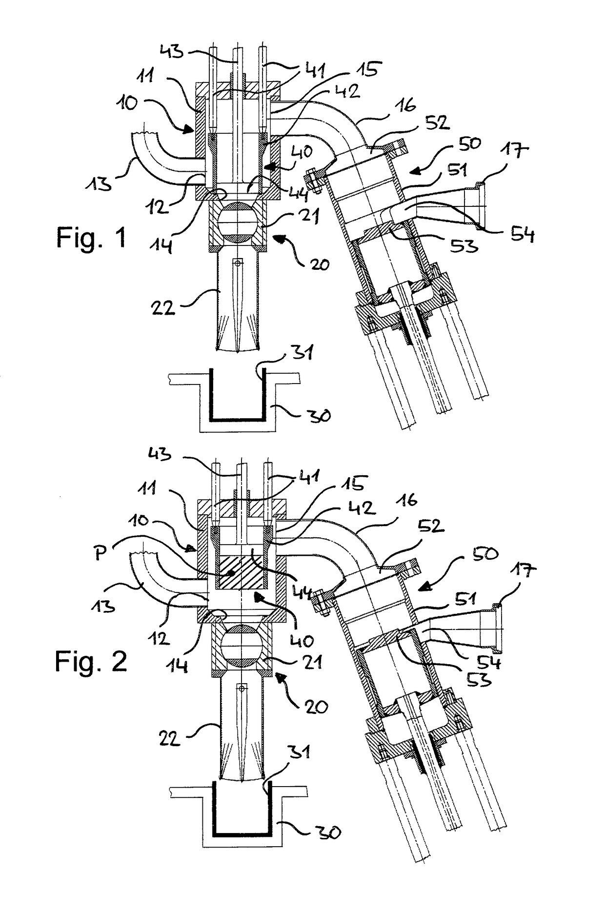
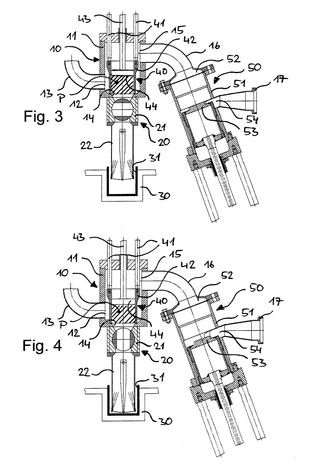
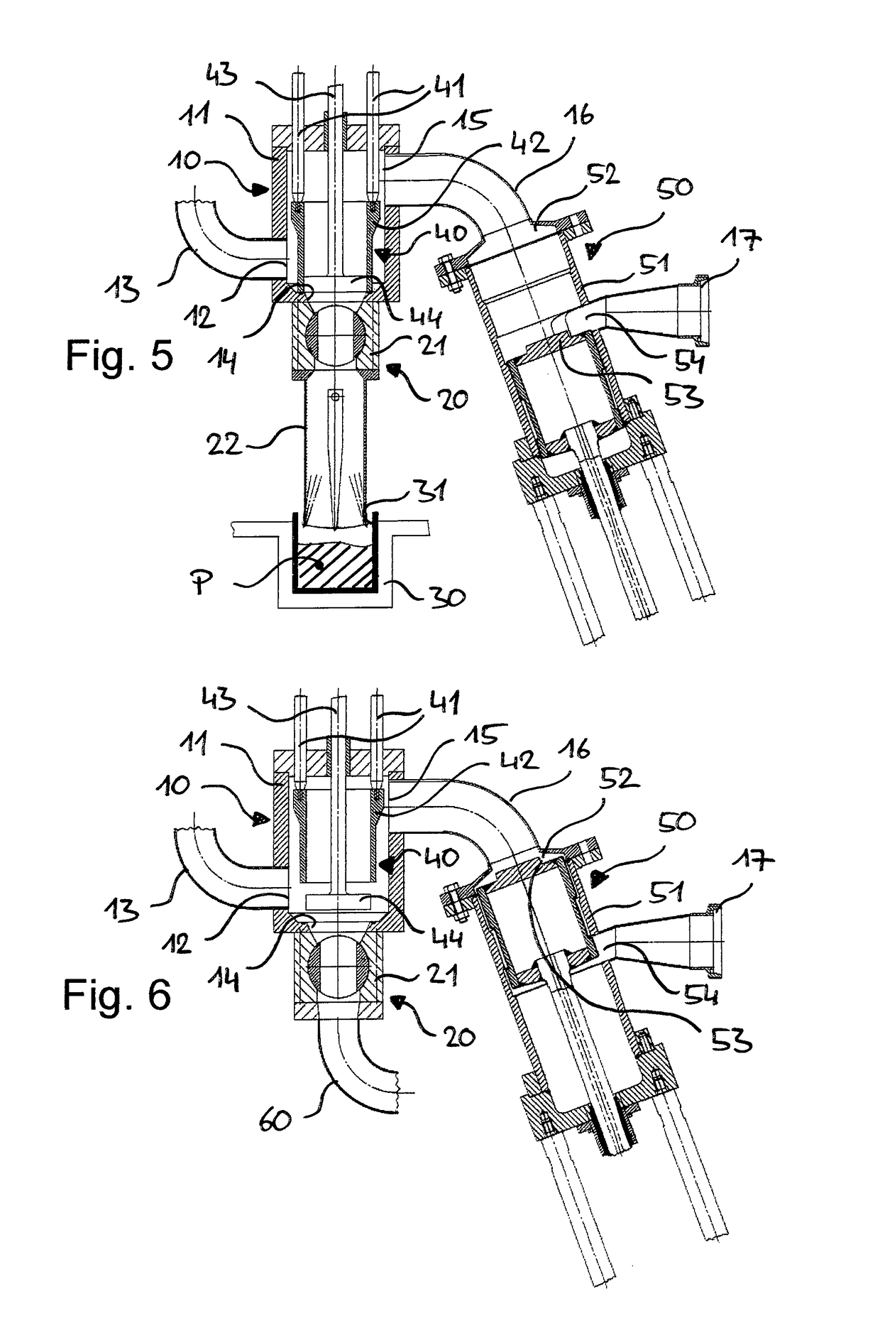
Furthermore, it has been shown that the abovementioned problem can be manifested in the case of packaging machines of the type in question in that, in the event of processing such products which are highly sensitive in respect of separating out or crystallizing out, in particular during temporary and also brief downtimes of the packaging machine or during restarting of same, erroneous meterings and / or defective product portions occur which have to be sluiced out and disposed of because the product residues remaining in the packaging machine no longer have the required quality.
Consequently, the packaging machine should be entirely flushed prior to each start-up, which is complicated and leads to undesirable downtimes. The same may be the case in the event of very slow metering and an associated, very slow supply of product into the metering chamber, wherein slow meterings may, on the other hand, be required if the pasty product is also sensitive to the mechanical forces brought about thereon in the metering chamber by the metering member.
Consequently, in particular during downtimes of the packaging machine, for example at night, or else in the event of only brief operating interruptions, there is, as before, the problem that the product crystallizes out in the rotary slides forming the metering chambers, whereupon the rotary slides have to be completely disassembled, cleaned and reassembled because even “CIP” cleaning is not possible in situ.
The latter is caused especially by the fact that the rotary slides cannot be flushed through with a cleaning medium either in the position in which they open toward the line portion of the circulating line or in the position in which they open toward the outlet nozzle, particularly since the product also passes between the outer circumferential surface of the rotary slides, which is always in contact with said product, and the bearing shells of said rotary slides which cannot be cleaned at all in the fitted state.
Apart from the fact that the known metering device, because of the fixedly predetermined size of the metering chamber, is capable only of metering a corresponding, fixedly predetermined product portion, there is in particular the disadvantage, even in this case—if sensitive products of the abovementioned type are intended to be processed—that, even during short downtimes, the product crystallizes out in the metering chamber, after which the metering chamber has to be cleaned.
However, processing of in particular products of the abovementioned type that are sensitive to rapid crystallization is not possible by means of the known dispenser for a number of reasons.
Although, firstly, some metering members—the outer metering members—are operated in continuous flow because of their series connection, a desired partial flow which passes said metering members can nevertheless not be set since said partial flow is fixedly predetermined by the necessary metering volume of the middle metering member which cannot be operated in continuous flow.
Secondly, in the event of even only short downtimes of the dispenser, the product which is sensitive in respect of crystallizing out would directly crystallize out because said product can only be removed from the line portion equipped with the metering members via the metering outlets, from where said product would have to be discarded.
However, it has proven disadvantageous firstly that circulation of the product through the metering chamber during downtimes of the dispenser appears to be possible only when the metering piston remains continuously in operation because the piston stroke is absolutely necessary for pumping the product through the metering chamber, which in turn means that the setting of a desired ratio of metered and recirculated product is not possible.
Secondly, the known dispenser does not permit what is referred to as CIP cleaning, during which said dispenser could be flushed by means of a cleaning fluid without having to disassemble the dispenser.
Said disassembly is caused by the fact that the metering piston which enters into contact on its lower end side with the product located in the metering chamber, if the metering chamber including its feed and removal lines is flushed with a cleaning fluid, can also come into contact only on its lower end side with the cleaning fluid, and therefore product residues which have been concentrated radially between the metering piston and the circumferential wall of the metering chamber after a plurality of piston strokes cannot be completely removed, as would absolutely be necessary, however, for foodstuff applications.

Method used


Image

  • Method for packaging liquid or pasty products and packaging machine suitable for this purpose
  • Method for packaging liquid or pasty products and packaging machine suitable for this purpose
  • Method for packaging liquid or pasty products and packaging machine suitable for this purpose

Examples


Embodiment Construction

[0044]FIGS. 1 to 3 schematically reproduce an exemplary embodiment of a metering unit of a packaging machine (otherwise not illustrated specifically) for packaging a liquid and / or pasty packaging product which is sensitive to untimely separating out or crystallizing out, such as, for example, margarine. The packaging machine can otherwise be substantially configured as per the prior art and in particular can have a plurality of metering units, which are operated in parallel, of the type shown.

[0045]The metering unit comprises a metering chamber 10, the cylindrical, although not necessarily circularly cylindrical, housing 11 of which firstly has an inlet 12, for example an inlet which leads radially into said housing and to which an inlet line 13 is connected and which serves for feeding the packaging product into the metering chamber 10, for example by means of a pump (not shown) connected to the inlet line 13. The housing 11 of the metering chamber 10 secondly has a metering outlet...


PUM

PropertyMeasurementUnit
volumeaaaaaaaaaa
radial distanceaaaaaaaaaa
viscousaaaaaaaaaa

Abstract

A method for the portioned packaging of liquid or pasty products using a packaging machine. The product is fed via an inlet to a metering chamber, being metered in the metering chamber by a metering member to form a product portion, and the product portion being fed via a metering outlet to a package. In order to avoid impairments of products which are sensitive to crystallizing out in the inoperative state, the metering chamber is operated in continuous flow in at least one operating state of the packaging machine from the following group: downtimes of the packaging machine, start-up of the packaging machine and operation of the packaging machine, by the product—whether entirely or in a partial flow—being removed entirely or partially from the metering chamber past the metering member via an outlet provided in addition to the metering outlet and being recirculated.

Description

[0001]This application is the national stage of PCT / EP2015 / 001559, filed on Jul. 29, 2015 and claiming Paris convention priority from DE 10 2014 011 075.3, filed Jul. 30, 2014.BACKGROUND OF THE INVENTION[0002]The invention relates to a method for the portioned packaging of liquid and / or pasty products by means of a packaging machine by the product being fed via at least one inlet of a metering chamber, being metered in the metering chamber by means of at least one metering member with an axially shiftable metering piston to form at least one product portion, and the at least one product portion being fed via at least one metering outlet to a package wherein the metering chamber is operated in a continuous flow in at least one operating state of the packaging machine from the following group[0003]downtimes of the packaging machine,[0004]start-up of the packaging machine, and[0005]operation of the packaging machine,[0006]by the product being removed entirely or partially from the mete...

Claims


Application Information

Patent Timeline
Patent Type & Authority Patents(United States)
IPC IPC(8): B65B37/06B65B37/20B65B3/32B65B39/00G01F11/16B65B43/59B65B3/12
CPCB65B37/06B65B3/12B65B3/32B65B37/20B65B39/003B65B43/59G01F11/16B65B39/001B65B2210/06G01F11/04
Inventor FRANZ, MAIK
Owner BENHIL GMBH
Why Eureka
Try Eureka