Expansion valve
a technology of expansion valve and valve section, which is applied in the direction of valve housing, valve operating means/release devices, lighting and heating apparatus, etc., can solve the problems that the provision of a throttle passage alone downstream of a valve section is not sufficient to reduce the above mentioned noise, and achieve the effect of preventing or minimizing the generation of noise, preventing or minimizing the generation of impact sound caused by the collision of liquid stagnation with subsequent refrigeran
- Summary
- Abstract
- Description
- Claims
- Application Information
AI Technical Summary
Benefits of technology
Problems solved by technology
Method used
Image
Examples
first embodiment
[0030][First Embodiment]
[0031]The embodiment embodies an expansion valve of the present invention in a form of a thermostatic expansion valve applicable to a refrigeration cycle in an automotive air conditioner. The refrigeration cycle includes a compressor for compressing a circulating refrigerant, a condenser (external heat exchanger) for condensing the compressed refrigerant, a receiver for separating the condensed refrigerant into gas and liquid, an expansion valve for throttling and expanding the separated refrigerant and delivering the resulting spray of refrigerant, and an evaporator (internal heat exchanger) for evaporating the misty refrigerant to cool the air in a vehicle interior by evaporative latent heat. For convenience of description, detailed description of components other than the expansion valve will be omitted herein.
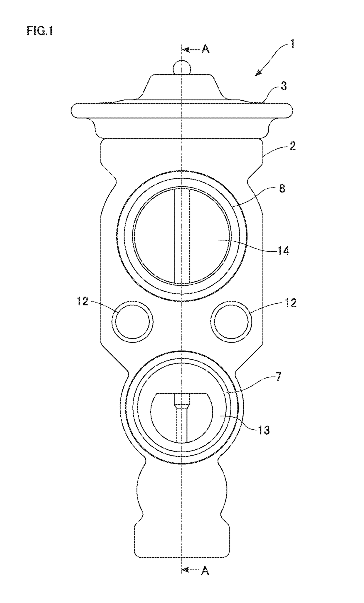
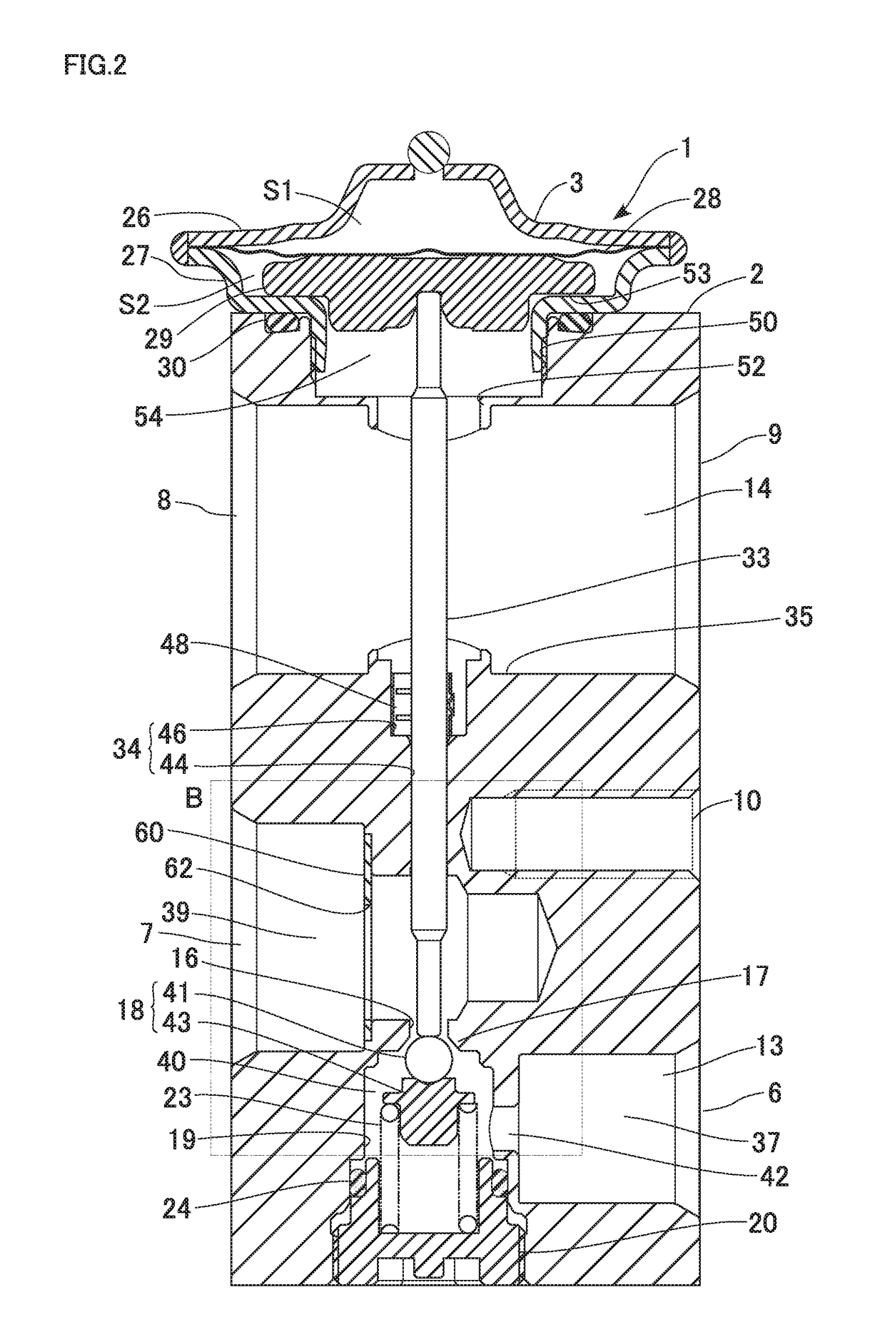
[0032]FIG. 1 is a front view of the expansion valve according to the first embodiment. FIG. 2 is a cross-sectional view along arrows A-A in FIG. 1. ...
second embodiment
[0067][Second Embodiment]
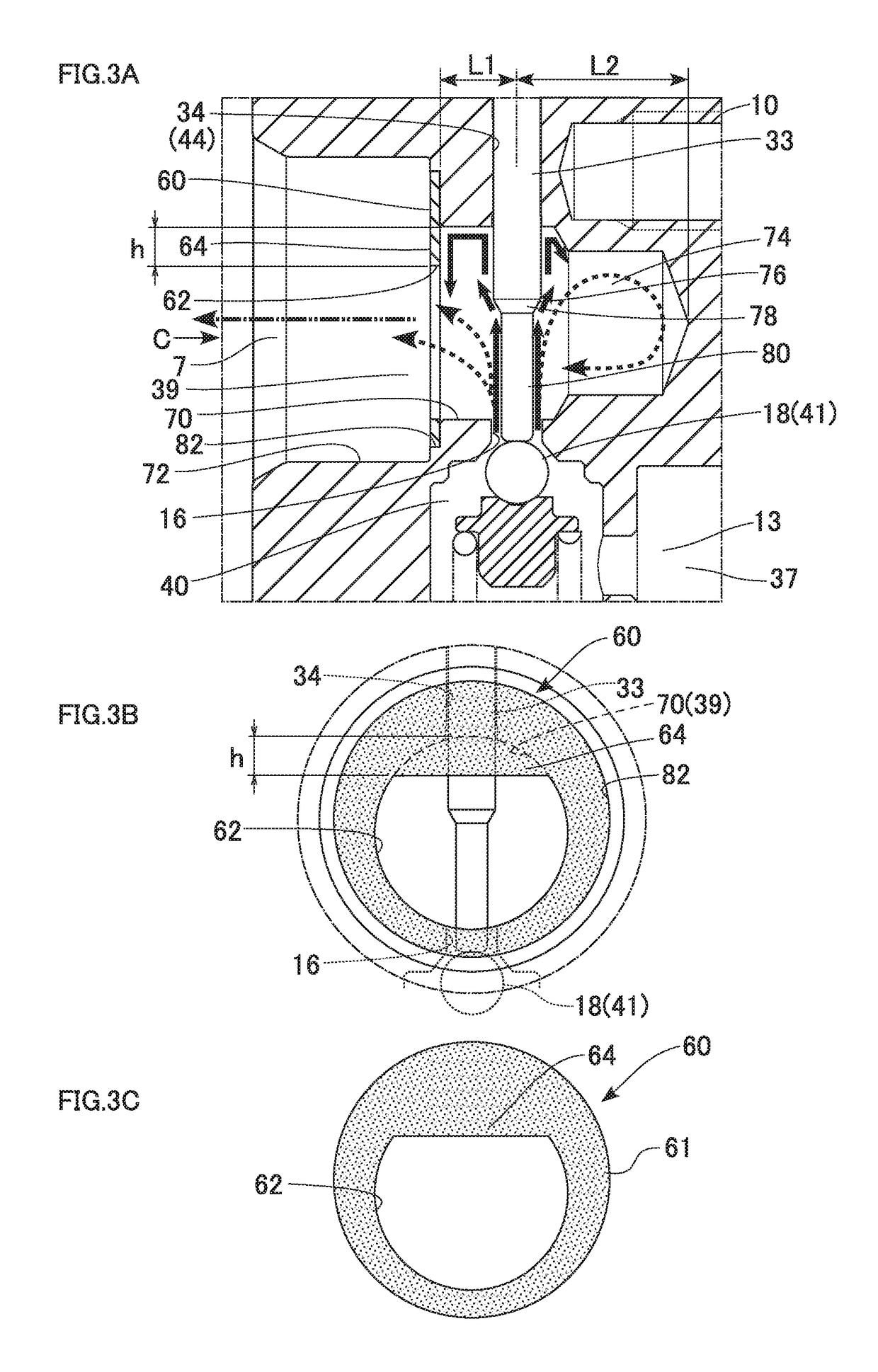
[0068]An expansion valve of the present embodiment is different from that of the first embodiment in the shape of the plate and the method for mounting the plate. The following description will focus on the differences from the first embodiment, and components similar to those in the first embodiment will be designated by the same reference numerals and the description thereof will be omitted. FIGS. 8A to 8C are diagrams illustrating a structure of a main part of the expansion valve according to the second embodiment. FIG. 8A is a partially-enlarged cross-sectional view of a plate and a structure around the plate, and FIG. 8B is a view as seen in the direction of an arrow C in FIG. 8A. FIG. 8C is a front view of the plate.
[0069]As illustrated in FIGS. 8A and 8B, the large-diameter part 72 has an annular fitting recess 82 at the bottom, and a fitting hole 284 is formed at a predetermined position in the fitting recess 82. As also illustrated in FIG. 8C, a pla...
third embodiment
[0074][Third Embodiment]
[0075]An expansion valve of the present embodiment is different from those of the first and second embodiments in the shape of a plate (a plate member) and the method for mounting the plate. The following description will focus on the differences from the first and second embodiments. FIG. 10 is a cross-sectional view of the expansion valve according to the third embodiment. FIGS. 11A and 11B are diagrams illustrating a plate and a structure around the plate. FIG. 11A is a view as seen in the direction of an arrow C in in FIG. 10. FIG. 11B is a diagram illustrating a structure of the plate, in which an upper part is a front view and a lower part is a cross-sectional view taken along arrows E-E in the upper part. In FIGS. 11A and 11B, dotted lines represent a state before the plate is fixed to the downstream-side passage, and solid lines represent a state after the plate is fixed.
[0076]As illustrated in FIG. 10, in an expansion valve 301, a plate 360 is fixed ...
PUM
 Abstract
Description
Claims
Application Information
 - R&D
- Intellectual Property
- Life Sciences
- Materials
- Tech Scout
- Unparalleled Data Quality
- Higher Quality Content
- 60% Fewer Hallucinations
Browse by: Latest US Patents, China's latest patents, Technical Efficacy Thesaurus, Application Domain, Technology Topic, Popular Technical Reports.
© 2025 PatSnap. All rights reserved.Legal|Privacy policy|Modern Slavery Act Transparency Statement|Sitemap|About US| Contact US: help@patsnap.com


