Installation structure of one-way clutch

a one-way clutch and installation structure technology, which is applied in the direction of machine/engine, engine starter, vehicle sub-unit features, etc., can solve the problem of one-way clutch malfunction

Active Publication Date: 2019-02-05
TOYOTA JIDOSHA KK
View PDF6 Cites 1 Cited by
  • Summary
  • Abstract
  • Description
  • Claims
  • Application Information

AI Technical Summary

Benefits of technology

[0009]Aspects of the present disclosure has been conceived noting the foregoing technical problems, and it is therefore an object of the present disclosure is to provide an installation structure of a one-way clutch that can prevent malfunction of the one-way clutch caused by a damage of the rivet.
[0013]Thus, according to the illustrative example, the first clearance between one face of the flywheel and the top face of a head of the rivet is reduced to be narrower than a thickness of the stopper plate. According to the illustrative example, therefore, the head of the rivet will come into abutment with the flywheel if the rivet begins to come out of through holes of the stopper plate, the second rotary structure, and the housing plate toward the flywheel due to fall-off of an expanded tail of the rivet. In this situation, the tail end of the rivet may remain within the through hole of the stopper plate. For this reason, the stopper plate is allowed to rotate integrally with the housing plate and the second rotary structure even if the rivet begins to come out of the through holes of those members to prevent breakdown and malfunction of the one-way clutch.
[0014]In addition, according to the illustrative example, the second clearance between the inner face of the flywheel and the housing plate is narrower than the thickness of the head of the rivet. That is, if the head of the rivet falls off, the detached head may remain in the chamber of the flywheel. According to the illustrative example, therefore, jamming of the rotary structures will not be caused by the detached head so that malfunction of the one-way clutch can be prevented.
[0015]Further, since the head of the rivet is held in the chamber of the flywheel, an axial length, i.e., a thickness of the one-way clutch can be shortened or thinned.

Problems solved by technology

However, if the tail of the rivet is not expanded suitably, or if the head or the tail of the rivet falls out, the outer race and the disc plate would be loosened to cause malfunction of the one-way clutch.

Method used


Image

  • Installation structure of one-way clutch
  • Installation structure of one-way clutch
  • Installation structure of one-way clutch

Examples


Embodiment Construction

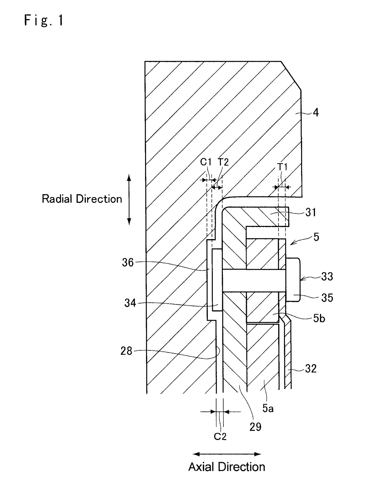
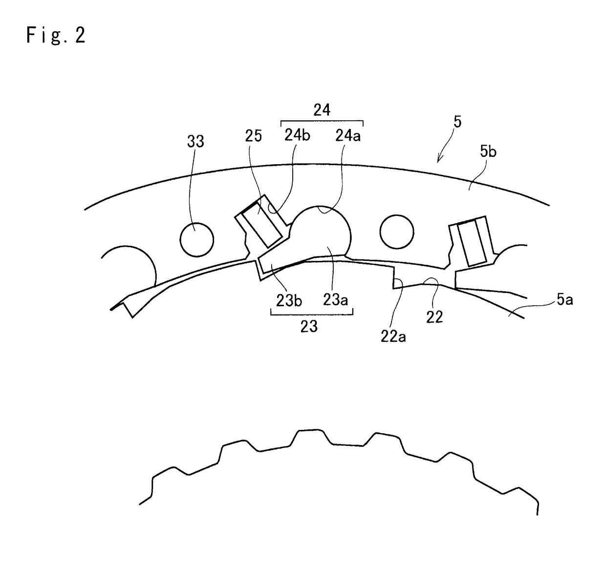
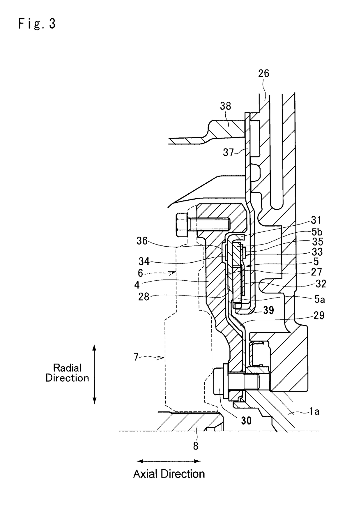
[0023]Referring now to FIG. 6, there is shown one example of a powertrain in which the one-way clutch according to an illustrative example is arranged. A prime mover of the powertrain shown in FIG. 6 includes an engine (ENG) 1, a first motor (MG1) 2 and a second motor (MG2) 3, and a flywheel 4 is fitted onto an output (or crank) shaft 1a. In order to prevent an inverse rotation of the output shaft 1a of the engine 1 together with the flywheel 4, a one-way clutch 5 is also fitted onto the output shaft 1a between the flywheel 4 and the engine 1.

[0024]A damper device 7 is connected to the flywheel 4 through a torque limiter 6. In the torque limiter 6, a drive plate and a driven plate are brought into frictional contact to each other, and those plates are allowed to rotate relatively from each other when the drive plate is rotated by a torque greater than the friction acting therebetween. An input shaft 8 is connected to an input element of a power distribution device 9 to deliver torqu...


PUM


Abstract

An installation structure of a one-way clutch in which torque transmission is limited to one direction includes a flywheel, first and second rotary structures, housing and stopper plates, and a rivet. The first rotary structure is arranged coaxially with the flywheel while connected to an engine block. The second rotary structure is arranged coaxially with the first rotary structure while connected to the flywheel. The housing plate is disposed between the flywheel and the first and second rotary structures and arranged coaxially while connected to the second rotary structure. The stopper plate is attached to the second rotary structure to hold first rotary structure with the housing plate. The rivet fastens the stopper plate, the second rotary structure, and the housing plate. A first clearance between one face of the flywheel and a top face of a head of the rivet is narrower than a thickness of the stopper plate.

Description

CROSS-REFERENCE TO RELATED APPLICATIONS[0001]The present application claims the benefit of priority to Japanese Patent Application No. 2015-112110 filed on Jun. 2, 2015 with the Japanese Patent Office, the entire contents of which are incorporated herein by reference in entirety.BACKGROUND[0002]Field of the Disclosure[0003]The present disclosure relates to the art of an installation structure of a one-way clutch in which torque transmission is limited to one direction.[0004]Discussion of the Related Art[0005]JP-A-2008-223704 describes one example of a one way clutch fitted onto an output shaft of an engine. According to the teachings of JP-A-2008-223704, sprags are arranged between an outer race formed around a disc plate and an inner race fitted onto an outer race of a bearing supporting the one-way clutch. In the one-way clutch taught by JP-A-2008-223704, therefore, axial displacement of the outer race and the inner race is restricted by the disc plate and the bearing.[0006]In tur...

Claims


Application Information

Patent Timeline
Patent Type & Authority Patents(United States)
IPC IPC(8): F02N15/02B60K6/383B60K6/30B60K6/365B60K6/445F16D41/12
CPCF16D41/12B60K6/30B60K6/365B60K6/383B60K6/445Y10S903/96B60Y2400/427F16D2300/12F16D2300/22Y10S903/91Y10S903/913B60Y2200/92F16D41/00B60K6/405Y02T10/62
Inventor ENDO, TAKAHITONOBUYASU, SEITAROSUZUKI, YOSUKEKATO, KOICHIIWASE, YUJI
Owner TOYOTA JIDOSHA KK
Why Eureka
Try Eureka