
Current mode hysteretic buck converter with auto-selectable frequency locking circuit

a buck converter and auto-selectable technology, applied in the direction of electric variable regulation, process and machine control, instruments, etc., can solve the problems of inefficiency of buck converters and difficulties in designing converters' electromagnetic interference filters, etc., to achieve high efficiency and improve power efficiency

Active Publication Date: 2019-02-05
KOREA ADVANCED INST OF SCI & TECH
View PDF6 Cites 0 Cited by
  • Summary
  • Abstract
  • Description
  • Claims
  • Application Information

AI Technical Summary

Benefits of technology

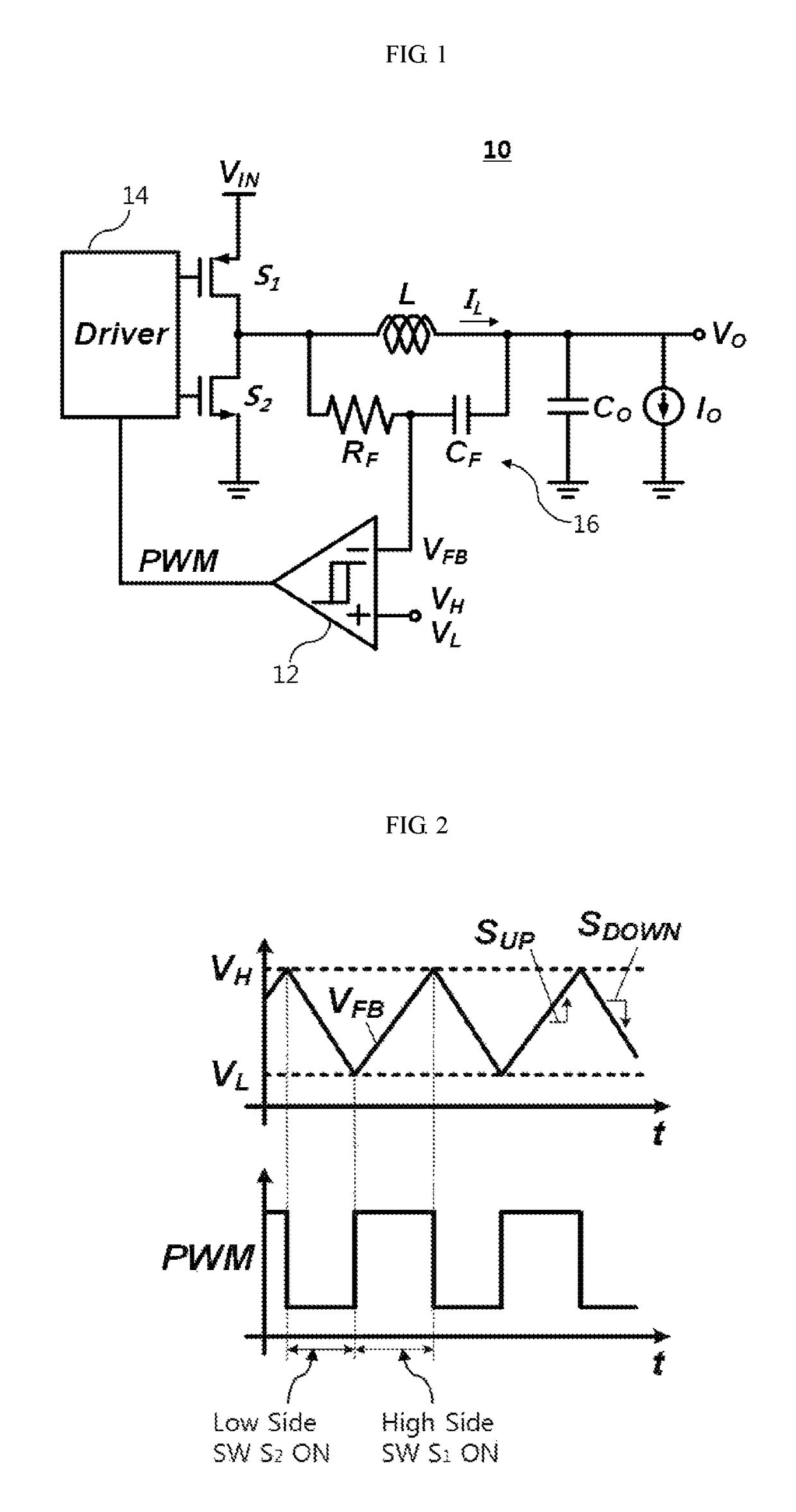
[0006]The present invention has been made under the recognition of the above-mentioned problems of the conventional art. Some embodiments of the present inventive concepts provide a current mode hysteretic buck converter having an automatic select frequency locking function that can lock the varying switching frequency of the current mode hysteretic buck converter, and achieve high efficiency in light load by adjusting the magnitude of the frequency locking value according to the load in order to compensate for the inherent PFM characteristics which may be lost by making the switching frequency be constant.
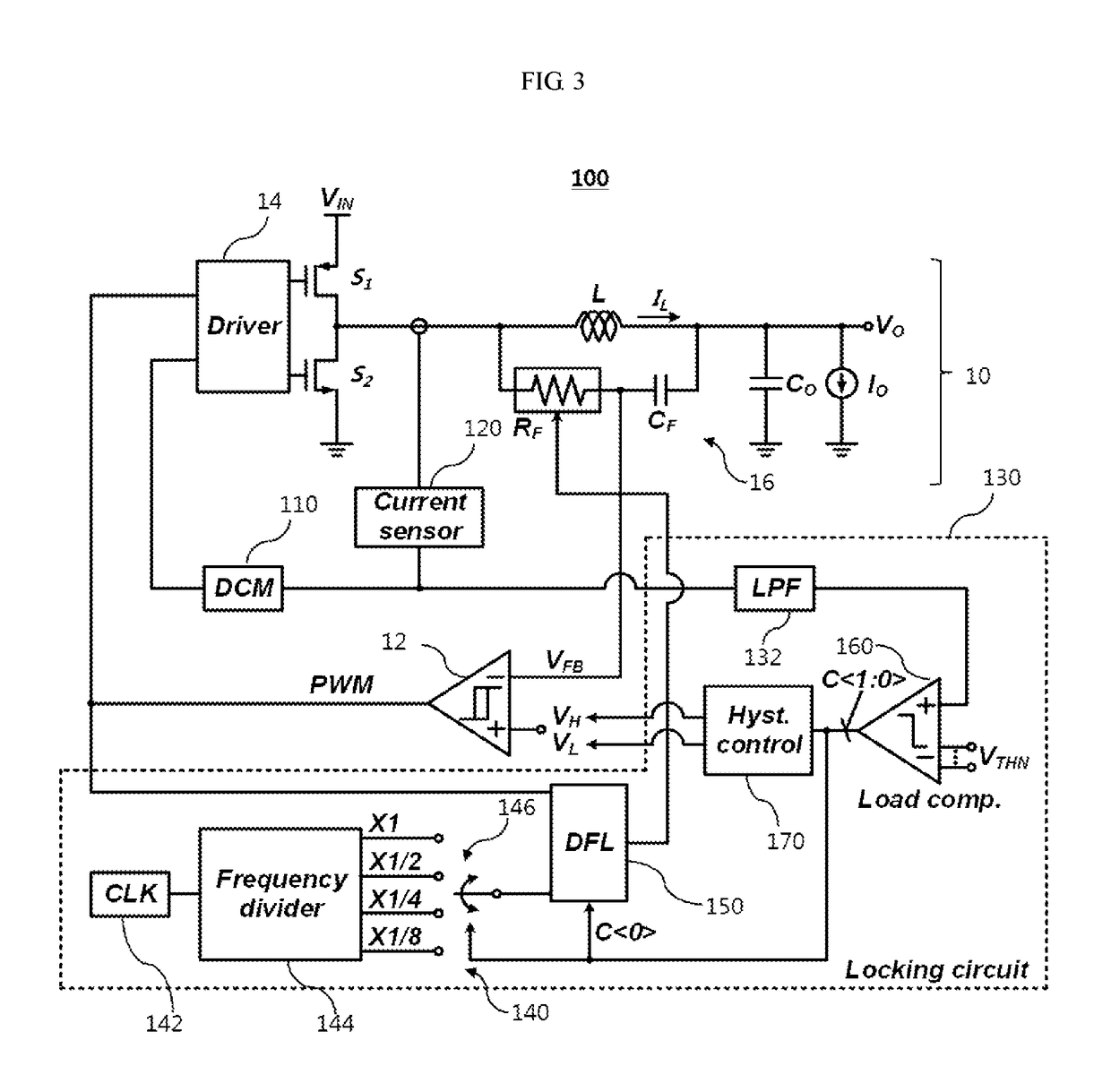
[0011]According to an exemplary embodiment, the frequency locking unit may automatically adjust the resistance value of the RC network when there is a change in an input voltage and a load current by changing hysteresis VH and VL of a hysteretic comparator set in advance according to a load condition.
[0013]According to an exemplary embodiment, the current mode hysteretic buck converter may be a circuit structure that converts a magnitude of an input voltage by switching the load to which first and second switch elements are connected, and further include a discontinuous conduction mode (DCM) circuit for preventing a reverse current flow by turning off the second switch element in an ON state when a reverse current flows to the second switch element from the load due to a low load current.
[0023]According to an exemplary embodiment, the frequency locking unit automatically may adjust the resistance value of the resistor-capacitor network when there is any change in an input voltage and a load current by changing hysteresis VH and VL of a hysteretic comparator set in advance according to a condition of the load.
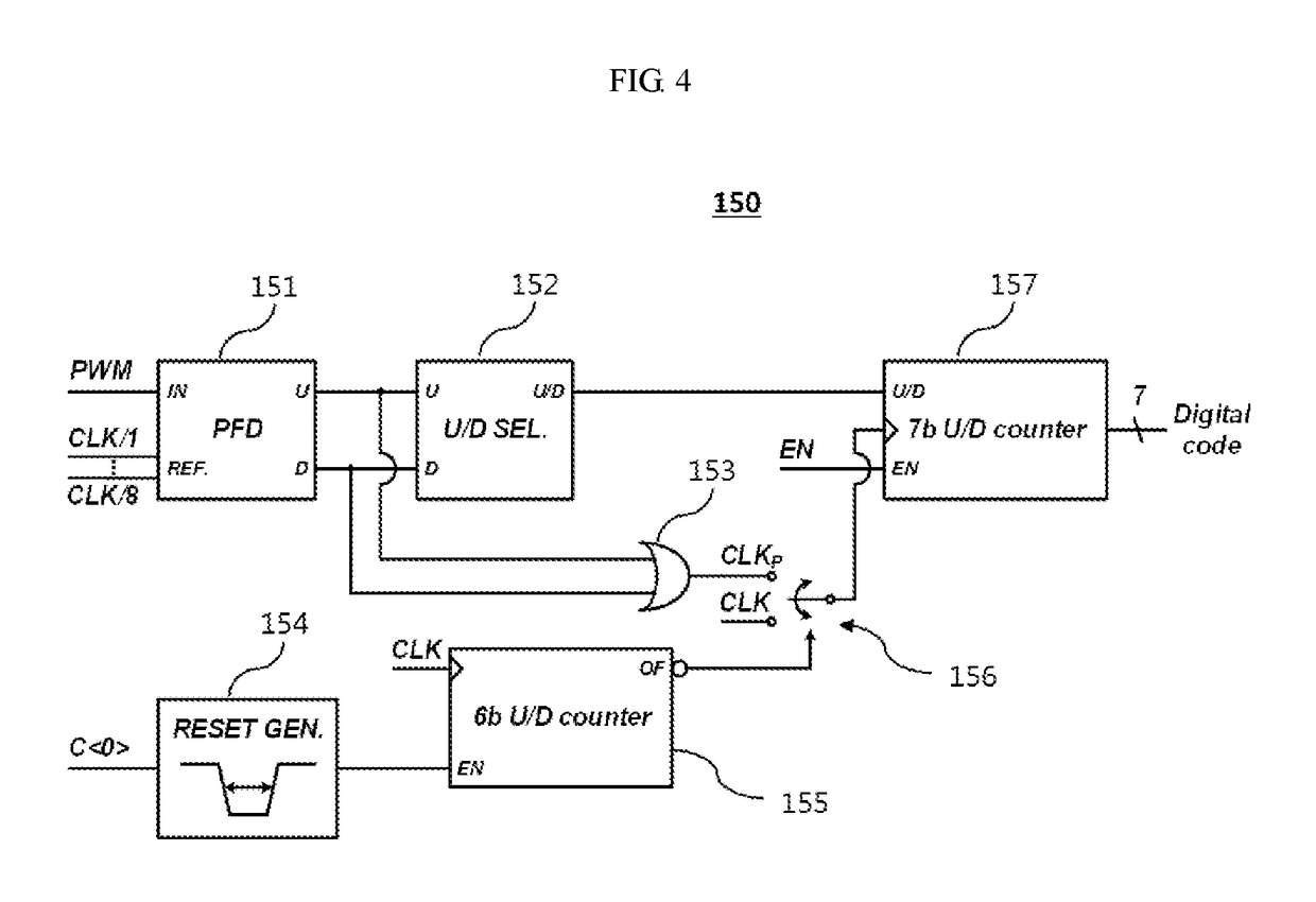
[0026]The auto-select frequency locking circuit for the current mode hysteretic buck converter according to the embodiments of the present invention having the above-described configuration locks the switching frequency of the hysteretic control but can achieve high efficiency by adjusting the size of the locked switching frequency depending on the load to compensate for the inherent PFM characteristics lost by taking a constant switching frequency, The auto-select frequency locking circuit may introduces a circuit for adjusting and locking the switching frequency according to a load in parallel with a basic current mode hysteretic buck converter. The basic operation principle of this frequency locking circuit is to control the switching frequency by adjusting the resistance value in the RC network connected in parallel to the inductor that is, by controlling the slope of the ripple signal VFB through comparing the reference frequency with the current switching frequency. In addition, the hysteresis VH and VL of the hysteretic comparator set in advance may be changed according to the load condition. Therefore, when there is any change in the input voltage and the load current, the frequency locking circuit can lock the variable switching frequency by initiating its operation and automatically adjusting a resistance value of the RC network.
[0027]The addition of the frequency locking circuit block according to the present invention to a current mode hysteretic buck converter can solve the inconsistent switching frequency problem of the conventional converters and improve power efficiency at light loads.

Problems solved by technology

The buck converter may be inefficient due to the switching loss that occurs during the ON / OFF operation of the power switch at light load.
However, the variable switching frequency may cause difficulties in designing the converter's electromagnetic interference (EMI) filter.

Method used


Image

  • Current mode hysteretic buck converter with auto-selectable frequency locking circuit
  • Current mode hysteretic buck converter with auto-selectable frequency locking circuit
  • Current mode hysteretic buck converter with auto-selectable frequency locking circuit

Examples


Embodiment Construction

[0034]Various example embodiments will be described more fully hereinafter with reference to the accompanying drawings, in which some example embodiments are shown. The present inventive concept may, however, be embodied in many different forms and should not be construed as limited to the example embodiments set forth herein. Rather, these example embodiments are provided so that this disclosure will be thorough and complete, and will fully convey the scope of the present inventive concept to those skilled in the art. In the drawings, the sizes and relative sizes of layers and regions may be exaggerated for clarity. Like numerals refer to like elements throughout.

[0035]It will be understood that, although the terms first, second, third etc. may be used herein to describe various elements, these elements should not be limited by these terms. These terms are used to distinguish one element from another. Thus, a first element discussed below could be termed a second element without de...


PUM


Abstract

A current mode hysteretic buck converter employing an auto-selectable frequency locking circuit is disclosed. The auto-selectable frequency locking type buck converter include a current mode hysteretic buck converter for converting an input DC voltage into a lower DC voltage, and a frequency locking unit for locking a switching frequency of the current mode hysteretic buck converter wherein the switching frequency is locked through adjusting a locking value of the switching frequency to be a predetermined value according to a size of a load. The buck converter is, based on the current mode hysteretic control, related to a circuit that locks the switching frequency of the converter to reduce the difficulty of designing electromagnetic interference (EMI) filters in the converter. In addition, the buck converter can improve the efficiency at light load by adjusting the switching frequency which is locked according to the load current.

Description

CROSS-REFERENCE TO RELATED APPLICATION[0001]This U.S. non-provisional application claims priority under 35 USC § 119 from Korean Patent Application No. 10-2016-0142978, filed on Oct. 31, 2016 in the Korean Intellectual Property Office (KIPO), the disclosure of which is hereby incorporated by reference in its entirety.BACKGROUND1. Technical Field[0002]Some embodiments of the present inventive concepts are directed to a converter device for converting an input direct current (DC) voltage into a DC voltage of a different level and outputting the same, and more particularly to a buck converter for processing the input DC voltage into an output voltage lower than the input voltage.2. Description of the Related Art[0003]A DC-DC converter is a device that outputs a regulated voltage of low ripple by processing an arbitrary input voltage into the voltage required by a load, and is often used to provide a supply voltage to an electronic device. The DC to DC power converters may be classified...

Claims


Application Information

Patent Timeline
Patent Type & Authority Patents(United States)
IPC IPC(8): H02M1/08H02M1/14H02M3/156H02M1/00
CPCH02M1/08H02M1/14H02M3/1563H02M3/156H02M2001/0054H02M2001/0032H02M1/0032Y02B70/10H03L7/193H02M1/0054
Inventor LEE, SANG-GUGSEO, JEONG-ILLIM, BAEK-MIN
Owner KOREA ADVANCED INST OF SCI & TECH
Learn More