Piezoelectric resonator unit and method of manufacturing the same

a piezoelectric resonator and piezoelectric technology, applied in the direction of electrical equipment, impedence networks, etc., to achieve the effect of easy mounting of piezoelectric resonators and improving detection accuracy

Active Publication Date: 2019-02-12
MURATA MFG CO LTD
View PDF10 Cites 1 Cited by
  • Summary
  • Abstract
  • Description
  • Claims
  • Application Information

AI Technical Summary

Benefits of technology

[0006]An object of the present invention, which has been devised against such a background, is to provide a piezoelectric resonator unit in which a piezoelectric resonator can be easily mounted at a predetermined position on a substrate and that can easily improve the accuracy in detecting the joining position where the cap is joined to the substrate and a method of manufacturing the piezoelectric resonator unit.
[0008]With the structure described above, since the widths w1 and w2 of the inside of the opening in the cap have the above relations, when the cap is joined to the protruding portion of the substrate, if a part of the end surface of the cap on one side becomes displaced inward beyond the protruding portion and an inner wall of the cap might interfere with the quartz crystal blank, a part of the end surface on the other side becomes displaced outward beyond the protruding portion. In this case, a gap is generated between the end surface of the cap and the substrate, and therefore the piezoelectric resonator is not hermetically sealed. Accordingly, it is possible to determine, by detecting whether the cap and the substrate are hermetically sealed, the conditions as to whether the cap and the substrate might be joined to each other in a state in which a part the end surface of the cap is displaced inward beyond the protruding portion (such as a state in which an inner wall of an edge portion of the cap or the joining material joined to the edge portion interferes with the piezoelectric resonator). Thus, it is possible to detect a defective product by using a method that is not related to electric characteristics. Accordingly, it is possible to easily improve the accuracy in detecting the joining position where the cap is joined to the substrate. Moreover, it is possible to improve reliability by reducing time-varying change in frequency characteristics due to hermetic sealing.
[0010]When the widths w1 and w2 of the inside of the opening in the cap have the above relations, it is possible to further reliably prevent the end surface of the cap to become displaced outward beyond the protruding portion and to reduce the size of the piezoelectric resonator unit. Accordingly, it is possible to reduce size and increase reliability.
[0017]With the method described above, since the widths w1 and w2 of the inside of the opening in the cap have the above relations, when the cap is joined to the protruding portion of the substrate, if a part of the end surface of the cap on one side becomes displaced inward beyond the protruding portion and an inner wall of the cap might interfere with the quartz crystal blank, a part of the end surface on the other side becomes displaced outward beyond the protruding portion. In this case, a gap is generated between the end surface of the cap and the substrate, and therefore the piezoelectric resonator is not hermetically sealed. Accordingly, it is possible to determine, by detecting whether the cap and the substrate are hermetically sealed, the conditions as to whether the cap and the substrate might be joined to each other in a state in which a part the end surface of the cap is displaced inward beyond the protruding portion (such as a state in which an inner wall of an edge portion of the cap or the joining material joined to the edge portion interferes with the piezoelectric resonator). Thus, it is possible to detect a defective product by using a method that is not related to electric characteristics. Accordingly, it is possible to easily improve the accuracy in detecting the joining position where the cap is joined to the substrate. Moreover, it is possible to improve reliability by reducing time-varying change in frequency characteristics due to hermetic sealing.
[0019]When the widths w1 and w2 of the inside of the opening in the cap have the above relations, it is possible to further reliably prevent the end surface of the cap to become displaced outward beyond the protruding portion and to reduce the size of the piezoelectric resonator unit. Accordingly, it is possible to reduce size and increase reliability.
[0020]With the present invention, it is possible to easily mount a piezoelectric resonator at a predetermined position on a substrate and to easily improve the accuracy in detecting the joining position where a cap is joined to the substrate.

Problems solved by technology

However, with such a structure, the mounting position of the piezoelectric resonator may vary, since an upper surface of the substrate (a surface on which the piezoelectric resonator is mounted) is flat and does not have a guide portion for positioning the piezoelectric resonator.

Method used


Image

  • Piezoelectric resonator unit and method of manufacturing the same
  • Piezoelectric resonator unit and method of manufacturing the same
  • Piezoelectric resonator unit and method of manufacturing the same

Examples


Embodiment Construction

[0031]Hereinafter, an embodiment of the present invention will be described. In the following descriptions with reference to the drawings, elements that are the same as each other or similar to each other are denoted by the same or similar numerals. The drawings show examples and the dimensions and shapes of elements in the drawings are schematic, and the embodiment does not limit the scope of the present invention.

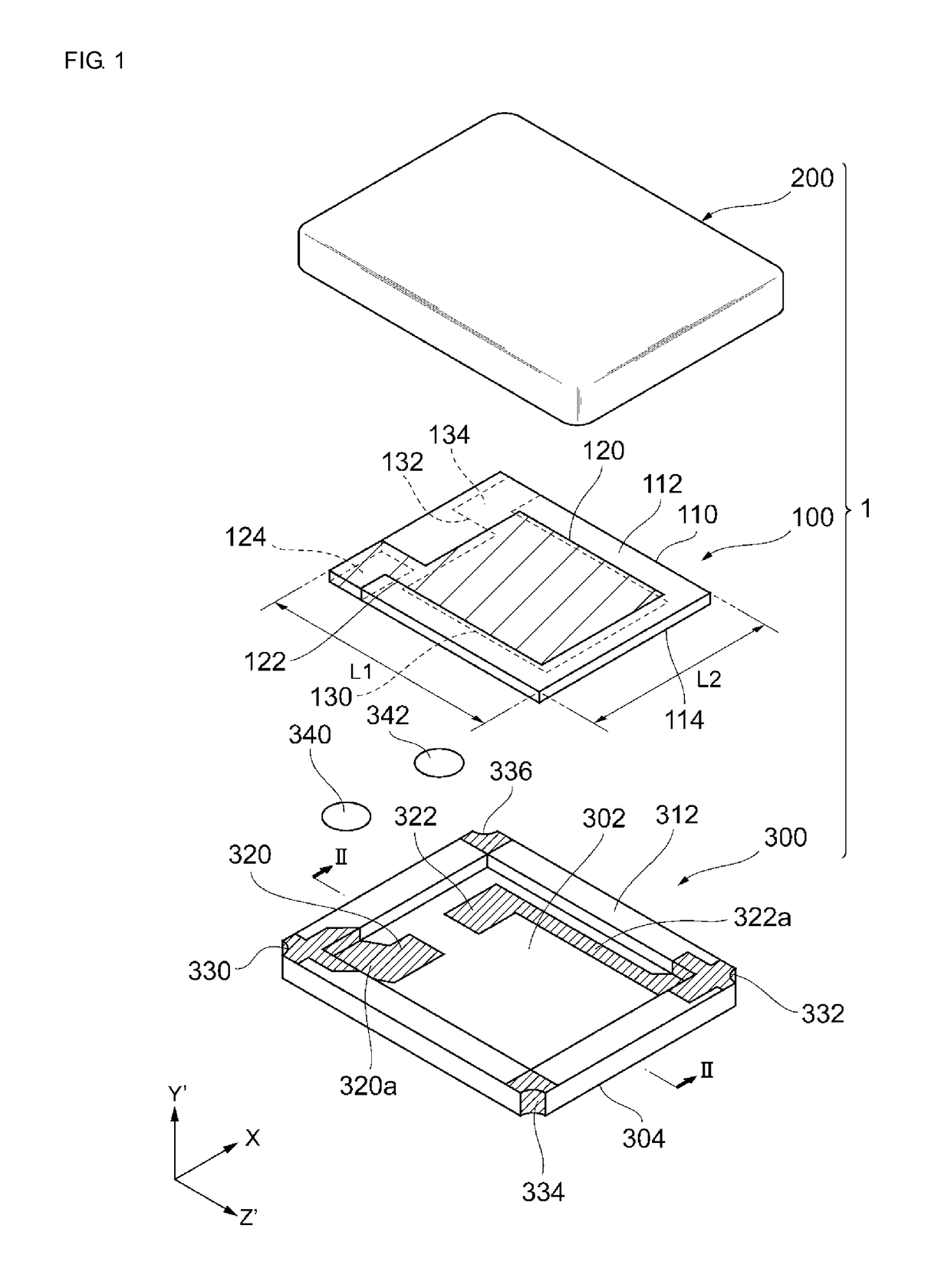
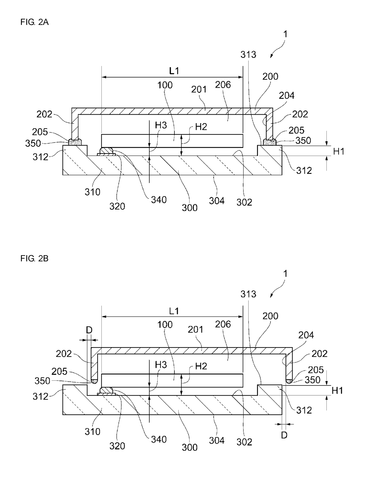
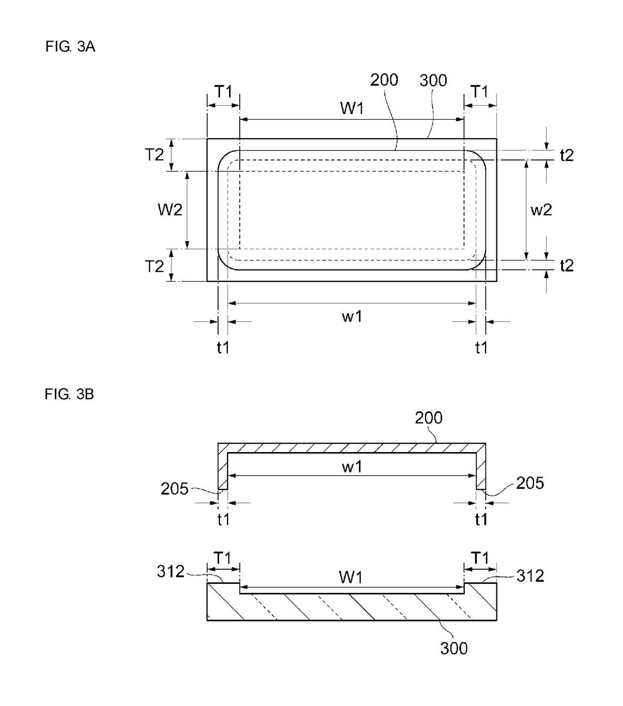
[0032]Referring to FIGS. 1 to 3C, a piezoelectric resonator unit according to the present embodiment will be described. FIG. 1 is an exploded perspective view of the piezoelectric resonator unit. FIGS. 2A and 2B are sectional views taken along line II-II of FIG. 1. FIGS. 3A to 3C illustrate the structures of a cap and a substrate of the piezoelectric resonator unit according to the present embodiment. A joining material, which is illustrated in FIGS. 2A and 2B, is not illustrated in FIG. 1.

[0033]As illustrated in FIG. 1, a piezoelectric resonator unit 1 according to the p...


PUM


Abstract

A piezoelectric resonator unit that includes a piezoelectric resonator, a substrate including a protruding portion, and a cap joined to the protruding portion. The piezoelectric resonator unit has a first relation of (W1+T1)≤w1<(W1+2T1), where, in a long-side sectional view, w1 is a width of an inside of an opening in the cap, T1 is a width of the protruding portion, and W1 is a width of the upper surface of the substrate between parts of the protruding portion; and has a second relation of (W2+T2)≤w2<(W2+2T2), where, in a short-side sectional view, w2 is a width of the inside of the opening in the cap, T2 is a width of the protruding portion, and W2 is a width of the upper surface of the substrate between parts of the protruding portion.

Description

CROSS REFERENCE TO RELATED APPLICATIONS[0001]The present application is a continuation of International application No. PCT / JP2016 / 063927, filed May 10, 2016, which claims priority to Japanese Patent Application No. 2015-109455, filed May 29, 2015, the entire contents of each of which are incorporated herein by reference.FIELD OF THE INVENTION[0002]The present invention relates to a piezoelectric resonator unit and a method of manufacturing the piezoelectric resonator unit.BACKGROUND OF THE INVENTION[0003]A piezoelectric resonator unit is an example of a piezoelectric device that is used as an oscillation device, a band-pass filter, or the like. A quartz crystal resonator unit, which is an example of a piezoelectric resonator unit, includes a quartz crystal resonator and an enclosure that holds the quartz crystal resonator. The enclosure includes a substrate, on which the quartz crystal resonator is mounted, and a cap (metal cover) that is joined to the substrate via a sealing mater...

Claims


Application Information

Patent Timeline
Patent Type & Authority Patents(United States)
IPC IPC(8): H03H9/10H03H3/02H03H9/13H03H9/19H03H9/02H03H9/05
CPCH03H9/10H03H3/02H03H9/02157H03H9/1021H03H9/132H03H9/19H03H9/0519H03H2003/022
Inventor KAIDA, HIROAKINOTO, KAZUYUKI
Owner MURATA MFG CO LTD
Why Eureka
Try Eureka