
Bypassing a load balancer in a return path of network traffic

a load balancer and network traffic technology, applied in the direction of digital transmission, data switching networks, electrical equipment, etc., can solve the problems of significant disruption and inefficiency of network throughput, serious security risks for the network, and load balancers creating bottlenecks in the path of network traffi

Active Publication Date: 2019-02-19
NICIRA
View PDF220 Cites 65 Cited by
  • Summary
  • Abstract
  • Description
  • Claims
  • Application Information

AI Technical Summary

Benefits of technology

The patent describes a method that allows two data compute nodes (DCNs) to communicate directly without using a load balancer. This is done by modifying the return traffic to reach the client machine directly, while the configuration of the server machine remains unchanged. The method uses a LB module that redirects the return traffic without needing to change the server machine's configuration. The LB module inserts an associated value as the reverse source address, which requires a mapping table to map the inserted value to its corresponding VIP address. The technical effect of this method is it improves communication speed and efficiency between the two DCNs.

Problems solved by technology

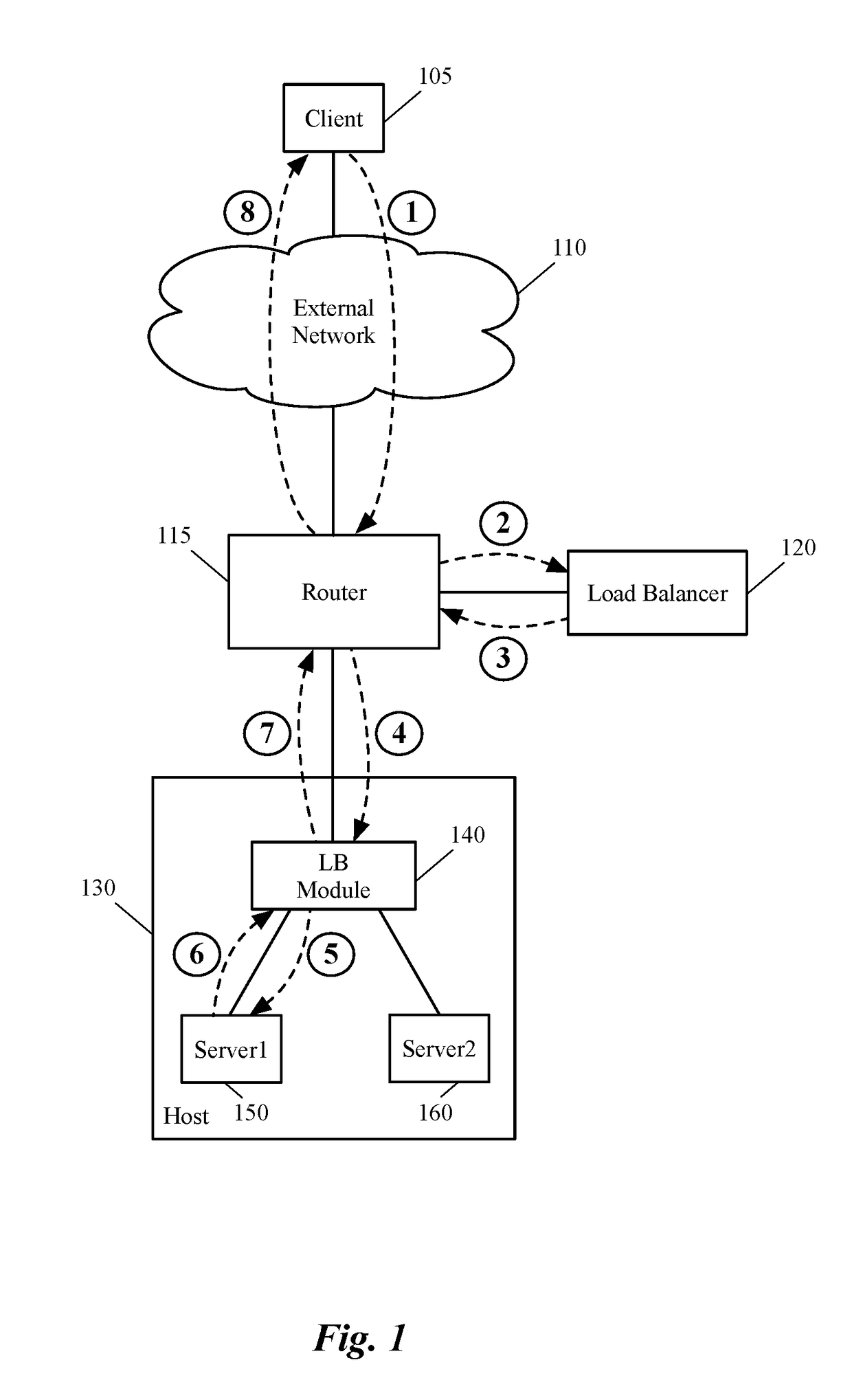
In some networks, however, load balancers create a bottleneck in the path of the network traffic since both incoming and outgoing traffic have to pass through the load balancers.
For example, in hosting systems, such as datacenters, where the north-south traffic is often asymmetric (i.e., the network traffic that leaves a hosting system is substantially more than the traffic that enters it), load balancers can cause significant disruption and inefficiency in network throughput.
As such, a traditional DSR load balancer either cannot process higher network layer protocols (e.g., transport layer or application layer protocols), or if it can, the load balancer can cause serious security risks for the network (e.g., malicious network attacks such as DDoS attacks).

Method used


Image

  • Bypassing a load balancer in a return path of network traffic
  • Bypassing a load balancer in a return path of network traffic
  • Bypassing a load balancer in a return path of network traffic

Examples


Embodiment Construction

[0039]In the following detailed description of the invention, numerous details, examples, and embodiments of the invention are set forth and described. However, it should be understood that the invention is not limited to the embodiments set forth and that the invention may be practiced without some of the specific details and examples discussed.

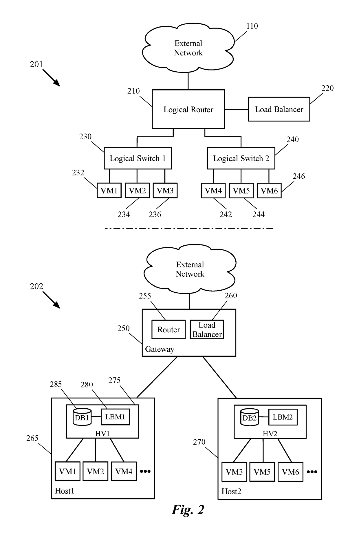
[0040]Some embodiments provide a method that allows a first data compute node (DCN) to forward outgoing traffic directly to a second DCN in spite of receiving the incoming traffic from the second DCN through a load balancer. That is, the return traffic's network path from the first DCN (e.g., a server machine) to the second DCN (e.g., a client machine) bypasses the load balancer, even though a request that initiated the return traffic is received through the load balancer. The method of some embodiments does not require any changes in the configuration of the first DCN (e.g., the server) in order to bypass the load balancer. That is, even th...


PUM


Abstract

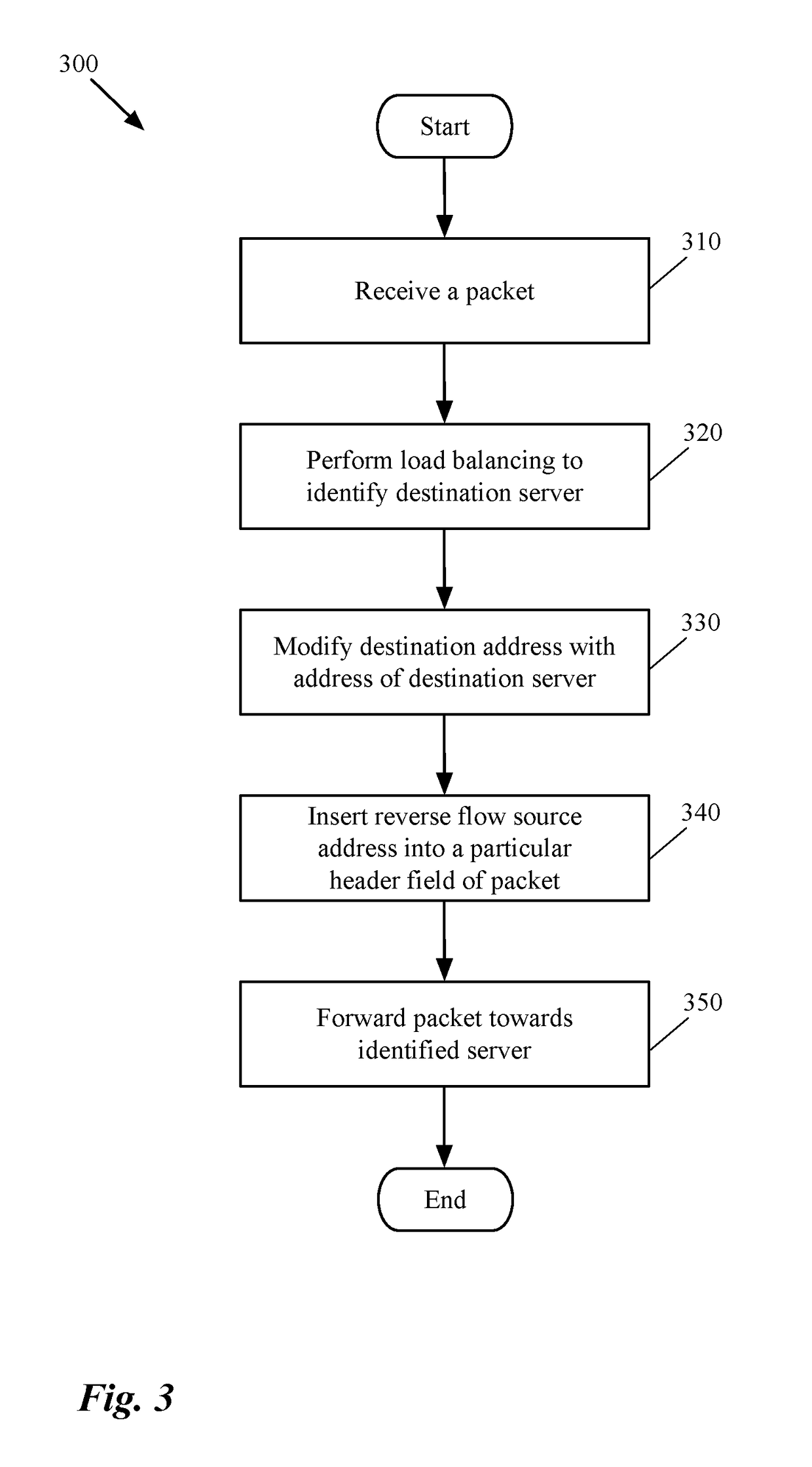
Some embodiments provide a method that allows a first data compute node (DCN) to forward outgoing traffic to a second DCN directly in spite of receiving the incoming traffic from the second DCN through a load balancer. That is, the return traffic's network path from the first DCN to the second DCN bypasses the load balancer, even though a request that initiated the return traffic is received through the load balancer. The method receives a first data message from a load balancer to be sent to a DCN. After identifying a particular address embedded in the data message by the load balancer, the method generates a table entry, based on source and destination addresses of the data message and the identified address. This entry is used for modifying a source address of a subsequent data message received from the DCN in response to the data message.

Description

BACKGROUND[0001]In networking, load balancers are traditionally used to distribute network and application traffic across a number of servers. In some networks, however, load balancers create a bottleneck in the path of the network traffic since both incoming and outgoing traffic have to pass through the load balancers. For example, in hosting systems, such as datacenters, where the north-south traffic is often asymmetric (i.e., the network traffic that leaves a hosting system is substantially more than the traffic that enters it), load balancers can cause significant disruption and inefficiency in network throughput. To get around this bottleneck, traditional load balancer vendors have used a technique called Direct Server Return (DSR) to be implemented by the load balancers, which modifies the traffic flow by permitting the server to respond directly to the client. The direct response to clients relieves the network load balancer of the need to handle the heavy return traffic.[000...

Claims


Application Information

Patent Timeline
Patent Type & Authority Patents(United States)
IPC IPC(8): H04L12/707H04L12/721H04L29/08H04L29/06H04L12/851H04L45/24
CPCH04L45/22H04L45/34H04L69/22H04L47/2483H04L67/1038H04L45/38H04L67/1004H04L61/2521
Inventor KANCHERLA, MANIJAIN, JAYANTSENGUPTA, ANIRBAN
Owner NICIRA
Learn More