Chip sweeping robot

a chip sweeping and robot technology, applied in the field of chip sweeping robots, can solve the problems of large amount of chips scattered, uneven sweeping results among workers, damage to workpieces or any of the tools, etc., and achieve the effect of automatic sweeping a wide range of efficiently

Inactive Publication Date: 2019-02-26
MITSUBISHI HEAVY IND MACHINE TOOL CO LTD
View PDF18 Cites 10 Cited by
  • Summary
  • Abstract
  • Description
  • Claims
  • Application Information

AI Technical Summary

Benefits of technology

[0031]As described above, according to the chip sweeping robot of the present invention, the rotating brush and the blade are provided in front of the robot body, which can autonomously travel on the upper surface of the table, sequentially from the front side to the back side in the traveling direction. Thus, the chip sweeping robot is capable of possessing adaptability to various machine tools and automatically sweeping a wide range efficiently.

Problems solved by technology

In consequence, a large amount of chips are scattered and deposited therein.
Then, if the scattered chips remain deposited on a machine sliding portion or on a workpiece, the chips may adversely affect a sliding action of the machine or cause damage to the workpiece or any of the tools.
However, if the workers sweep the chips by themselves in this way, it takes time and trouble for sweeping and what is more, sweeping outcomes may be uneven among the workers.

Method used


Image

  • Chip sweeping robot
  • Chip sweeping robot
  • Chip sweeping robot

Examples


embodiment

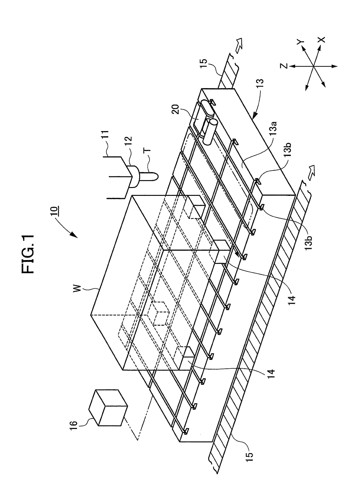
[0041]As shown in FIG. 1, a ram 11 and a table 13 are supported by a machine tool 10 in such a way as to be relatively movable in three orthogonal directions. For example, the ram 11 is movably supported in a Y-axis direction equivalent to a width direction of the machine and in a Z-axis direction equivalent to a vertical direction of the machine, while the table 13 is movably supported in an X-axis direction equivalent to a front-back direction of the machine.

[0042]In the ram 11, a main spindle 12 is rotatably supported about the Z axis. A tool T is detachably attached to a tip end of the main spindle 12. Meanwhile, a workpiece (an object to be machined) W is put on an upper surface 13a of the table 13 by use of jigs 14. Here, multiple T grooves 13b are formed in the upper surface 13a of the table 13 in such a way as to extend in the X-axis and Y-axis directions. The jigs 14 can be fixed to the T grooves 13b by using fixtures (not shown).

[0043]In the meantime, chip conveyors 15 are...


PUM


Abstract

There is provided a chip sweeping robot which is capable of possessing adaptability to various machine tools and automatically sweeping a wide range efficiently. To this end, a chip sweeping robot configured to sweep chips, which are scattered on an upper surface of a table of a machine tool at the time of machining a workpiece attached to the table, by traveling in accordance with a travel route set on the upper surface, includes: a robot body which autonomously travels on the upper surface; a rotating brush which sweeps the chips out forward in a traveling direction by being rotated from a lower side to an upper side forward in the traveling direction; and a blade which scoops out the chips, which pass through the rotating brush, forward in the traveling direction and sends the chips to a rotating region of the rotating brush.

Description

TECHNICAL FIELD[0001]The present invention relates to a chip sweeping robot, which is capable of automatically sweeping chips that are scattered in a machining process.BACKGROUND ART[0002]In the field of machining, NC machine tools have been widely adopted for the purpose of automation and manpower saving. Such a machine tool performs a continuous operation for a long time while automatically changing tools and workpieces. In consequence, a large amount of chips are scattered and deposited therein. Then, if the scattered chips remain deposited on a machine sliding portion or on a workpiece, the chips may adversely affect a sliding action of the machine or cause damage to the workpiece or any of the tools.[0003]A method of sweeping scattered chips by workers on their own has generally been adopted as a conventional chip sweeping method. However, if the workers sweep the chips by themselves in this way, it takes time and trouble for sweeping and what is more, sweeping outcomes may be ...

Claims


Application Information

Patent Timeline
Patent Type & Authority Patents(United States)
IPC IPC(8): B23Q11/00B08B13/00B08B1/04A46B13/00B08B1/00
CPCB23Q11/0075A46B13/00B08B13/00B08B1/04Y02P70/171B08B1/00A46B13/001A46B2200/3066Y02P70/10
Inventor MATSUMOTO, SHIGERUOKATANI, JUNICHI
Owner MITSUBISHI HEAVY IND MACHINE TOOL CO LTD
Why Eureka
Try Eureka