Drag reducing aerodynamic vehicle components and methods of making the same
a technology of aerodynamic vehicles and components, applied in the direction of vehicle body, vehicle body streamlining, domestic articles, etc., can solve the problems of limited forming operations of materials, achieve the effects of reducing air stagnation, and reducing air pressure and drag on the vehicl
- Summary
- Abstract
- Description
- Claims
- Application Information
AI Technical Summary
Benefits of technology
Problems solved by technology
Method used
Image
Examples
example 1
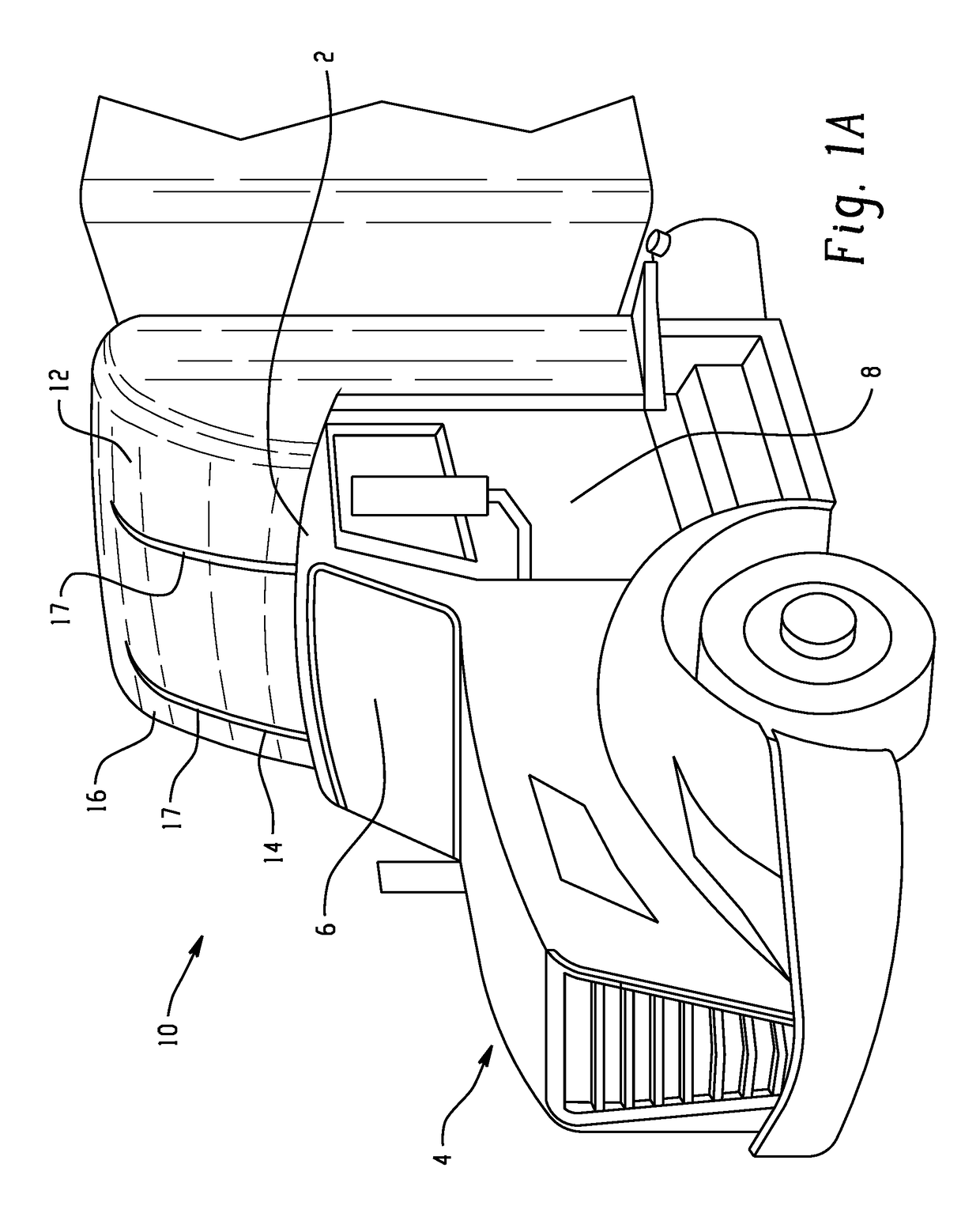
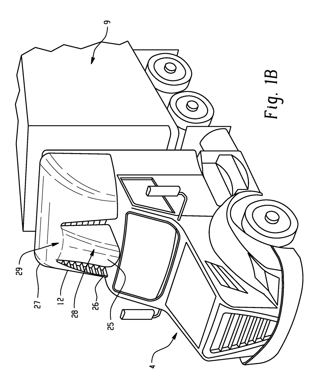
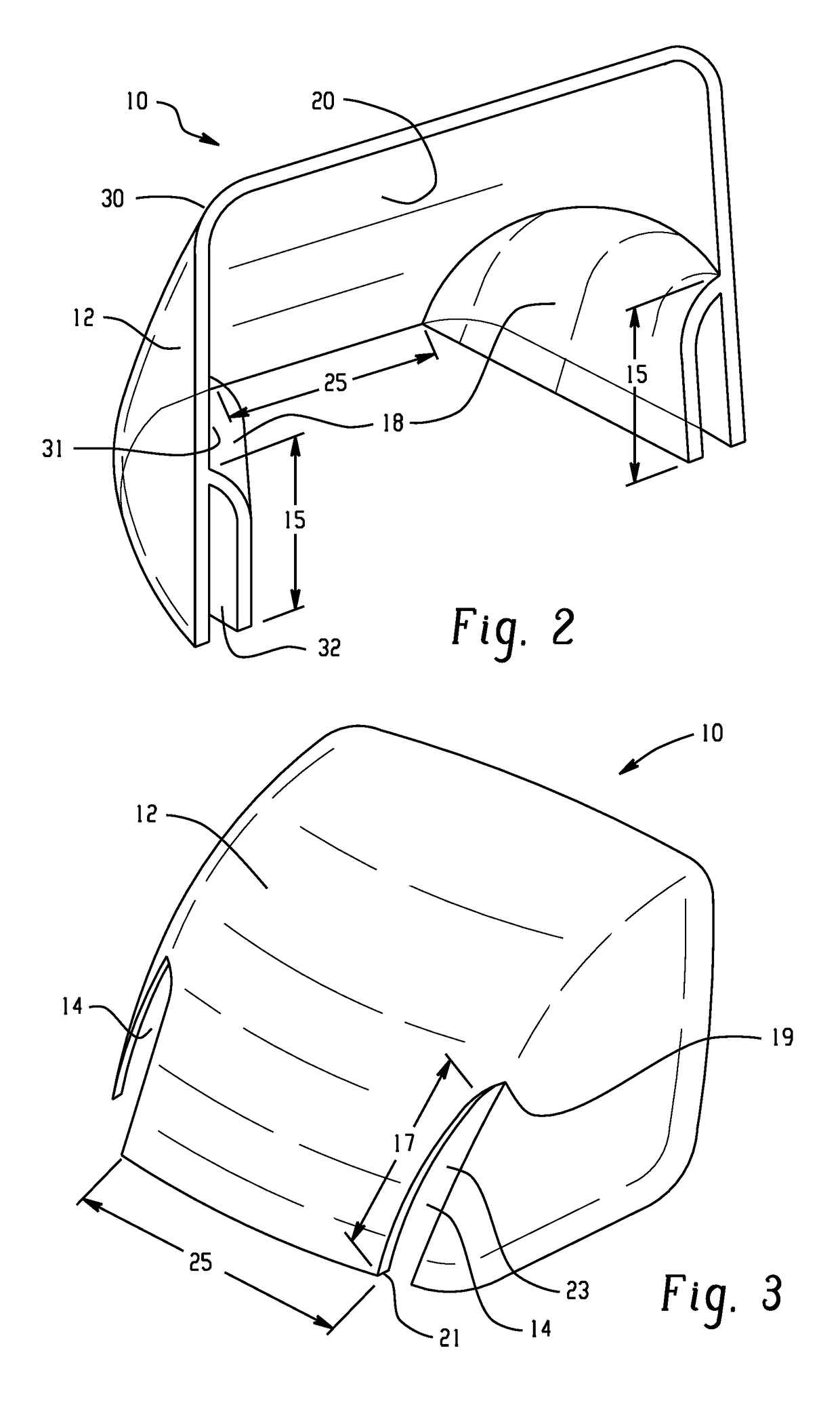
[0093]A roof fairing having the design shown in FIGS. 8 to 14 is tested (Sample 1) and compared to a baseline roof fairing (Comparative Example 2) (see FIG. 17). Drag is measured in drag counts for each design and the results are shown in FIG. 15 with a drag development plot showing the drag force accumulation along the length of a vehicle. “Drag counts” equal 0.001 coefficient of drag (CD). Total drag is equal to the sum of all drag forces on all parts of the vehicle, shown at the right side of FIG. 15, where X=20 meters (m). Reduction in cumulative drag at 6° yaw between the baseline and the optimized design is labelled 116 in FIG. 15 and is equal to 32 counts or 5.3%. Reduction in cumulative drag at 0° yaw between the baseline and the optimized design is equal to 4.4% for an overall reduction in drag of 4.9% as compared to a baseline roof fairing 110. Baseline roof fairing 110 has higher cumulative drag than the current roof fairing 112 as can be seen in FIG. 15. A 5.3% reduction...
example 2
[0094]A roof fairing having the design shown in FIG. 7 is tested and compared to a baseline roof fairing (see FIG. 17). Drag is measured in drag counts for each design and the results are shown in FIG. 16 with a drag development plot showing the drag force accumulation along the length of a vehicle. “Drag counts” equal 0.001 coefficient of drag (CD). Total drag is equal to the sum of all drag forces on all parts of the vehicle, shown at the right side of FIG. 16, where X=20 meters (m). Reduction in cumulative drag between the baseline and the optimized design is labelled 116 in FIG. 16 and is equal to 32 counts or 3.8%. Baseline roof fairing 110 has higher cumulative drag than the current roof fairing 114 as can be seen in FIG. 16. A 3.8% reduction in cumulative drag is observed between roof fairing 110 and roof fairing 114, resulting in a 1.9% reduction in fuel usage according to the 2:1 relationship between delta drag and fuel usage. In this example, vehicle drag was modeled under...
example 3
[0095]In this example, a roof fairing as shown in FIGS. 8 to 14 was analyzed for structural behavior under typical road driving conditions (i.e., inertial loading at 5 grams and air pressure loads at 75 mph (104.6 kph). The material chosen for Sample 3 is a mineral filled polycarbonate / acrylonitrile butadiene styrene (PC / ABS) alloy (CYCOLOY™, commercially available from SABIC's Innovative Plastics business) with a Young's Modulus (E-modulus) of 4,400 MegaPascals (MPa), paintability, and high low temperature impact. The results of the analysis are shown in Table 2. Frequency is measured in Hertz (Hz). Highway loads were considered at 5 G's in the horizontal plane of the roof fairing and 3 G in the vertical plane of the roof fairing. Additional pressure loads were also tested.
[0096]
TABLE 2Results of Structural AnalysisSampleMetricUnits3Natural FrequencyHertz (Hz)15Highway Loads (5G in Plane, 3G Vertical)Margin of Safety (yield)Safety Factor of 1.257.3Margin of Safety (ultimate)Safety ...
PUM
| Property | Measurement | Unit |
|---|---|---|
| wind averaged drag coefficient | aaaaa | aaaaa |
| speed | aaaaa | aaaaa |
| speed | aaaaa | aaaaa |
Abstract
Description
Claims
Application Information
 - R&D
- Intellectual Property
- Life Sciences
- Materials
- Tech Scout
- Unparalleled Data Quality
- Higher Quality Content
- 60% Fewer Hallucinations
Browse by: Latest US Patents, China's latest patents, Technical Efficacy Thesaurus, Application Domain, Technology Topic, Popular Technical Reports.
© 2025 PatSnap. All rights reserved.Legal|Privacy policy|Modern Slavery Act Transparency Statement|Sitemap|About US| Contact US: help@patsnap.com


