Skimmer for concentrating an aerosol

a technology of aerosol and concentrater, which is applied in the direction of dispersed particle separation, separation process, instruments, etc., can solve the problems of high concentration of aerosol, low concentration of concentrated aerosol, and ineffective focusing devices in separating the particle-rich core from the particle-depleted sheath flow, so as to improve the recovery effect of particl

Inactive Publication Date: 2011-01-25
ENERTECHNIX
View PDF24 Cites 8 Cited by
  • Summary
  • Abstract
  • Description
  • Claims
  • Application Information

AI Technical Summary

Benefits of technology

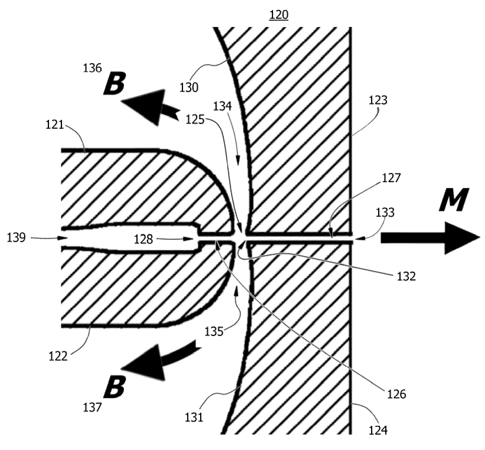
[0024]Within the body of the skimmer are two lateral flow channels in fluidic communication with the gas stream. The union of the lateral flow channels, the inlet raceway, and the collector channel forms a “crossed-tee” junction, and the virtual impact void is the mouth of the collector channel. The lateral flow channels bear sharply away from the long axis of flow and separate the frontend body members and the backend body members. The lateral flow channels are generally symmetrical and are formed between the downstream or “posterior” walls of the frontend body members and the upstream or “anterior” walls of the backend body members. Each of the lateral flow channels is characterized in that the upstream walls of the downstream body members (i.e. facing the lateral flow channels) are generally concavedly curved or contoured, that is, the lateral arms form a path for the bulk flow streamlines curve in an arc that is generally orthogonally or obtusely bending away from long axis of flow through the crossed tee junction, albeit ‘curvedly bending away’ and not perpendicular or straight walled. It can be said that the virtual impactor void is centered on a “concavedly curved” solid impactor surface. This is done to coherently port the bulk flow away from the minor flow by arcuately bending it more than 90 degrees, even more preferably more than 110 degrees, even more preferably more than 150 degrees, and most preferably about 180 degrees from the long axis direction of flow. It can be said that the throat of the device is configured to bend the bulk flow along an arcuate path away from the direction of the long axis of flow, the arcuate path bending more than 90°, in another embodiment more than 110°, and in another embodiment about 180° from the long axis of flow. In one embodiment, effectively, the bulk flow is directed into a “U-turn”. This leads to a more compact collector device and improves the collection efficiency by eliminating or reducing flow instability, wall separation, and stagnation zones around the virtual impact void and the throats of the lateral flow channels.
[0027]In a preferred embodiment, the chimneys and outlet ports lie between the inlet members of a palisaded linear array of concentrators. In a yet more preferred embodiment, the chimney and outlet ports penetrate multiple layers of a two-dimensional stack of linear arrays, forming a common outlet ductwork joined to an exhaust manifold, which in turn is fitted with a means for generating a suction pressure, such as a vacuum pump, blower, or other vacuum source. In practice, the flow resistance in each of the bulk flow channels and collector channels will establish the flow split of the device when operated with a common source of suction pressure source.
[0031]Uses of the present invention include detection of biological or chemical warfare agents in the form of aerosols, collection of industrial pollutant particles such as fly ash in a gas plume, sampling of air in buildings associated with “sick building” syndrome, collection of infectious or disease-causing organisms in hospitals and public spaces, the collection of radioactive particles, and collection of biological aerosols such as endotoxins, indoor and outdoor allergens, and so forth. It is also contemplated that the present invention may be used for the detection and collection of airborne particles associated with illegal drugs and explosives or their precursors. The concavedly curving lateral channel configuration disclosed here is discovered to be associated with improved particle recovery.

Problems solved by technology

Atmospheric aerosols from natural, anthropogenic, and industrial sources have long been recognized as a potential threat to human health.
One major challenge that must be addressed by all aerosol samplers is that many aerosols occur at extremely low concentrations, or may be only a small fraction of the urban background aerosol distribution.
But used in isolation such focusing devices are not effective in fractionating the particle-rich core from the particle-depleted sheath flow.
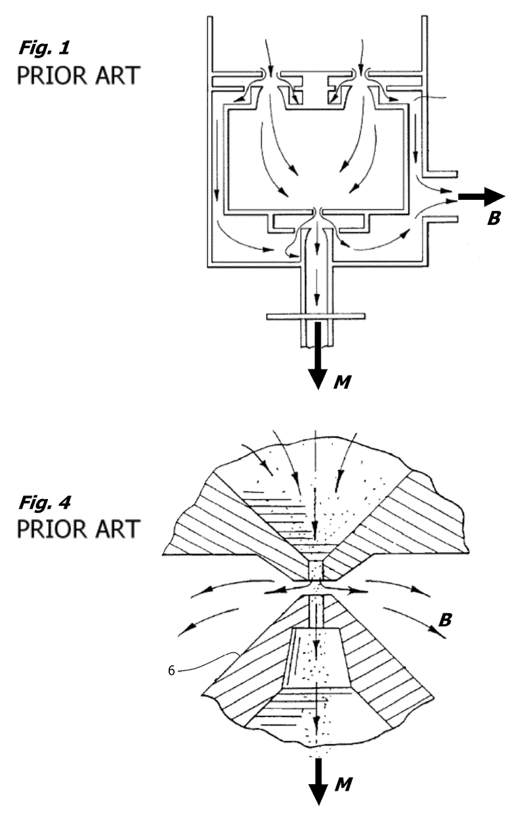
This early design of a virtual impactor, represented here in FIG. 1, is not readily scaleable for handling large air flows in a compact device and is expected to have a relatively high cutoff size.
This geometry, however, is associated with stagnation points and eddy instability at the point of flow separation that leads to particle loss by wall collisions and diversion with the bulk flow.
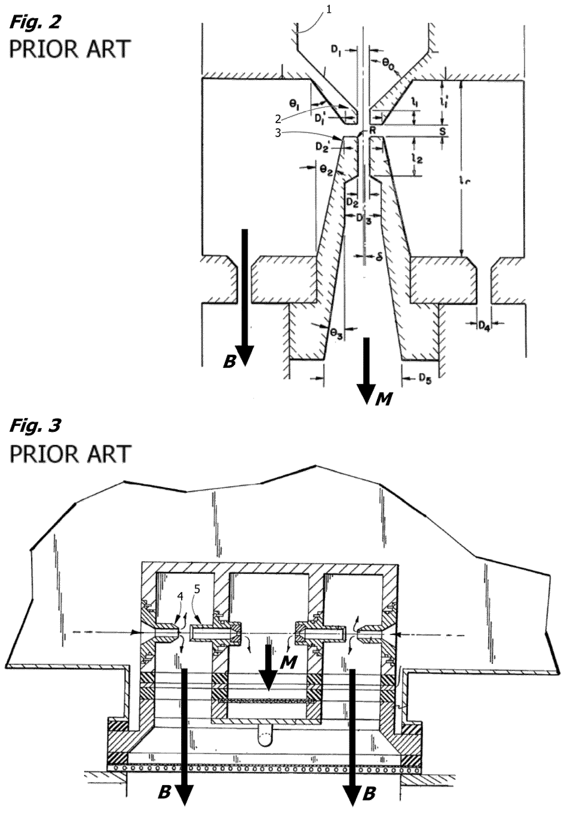
However, difficulties are reported due to impaction losses on the cone of the collection probe and to eddying around the virtual impact void.
Construction of these devices, particularly the acute angles of the nose, relies on difficult and expensive micromachining techniques.
This description is consistent with wall separation, which is accompanied by instability in the flow regime around the nose, and is not expected to result in higher efficiencies at higher flow rates and flow splits.
These separation plates, however, cannot be stacked because of mechanical interferences, and because pipeflow resistances rapidly lead to a decrease in pressure drop in the bulk flow exhaust from one layer to the next.
Construction of these devices also relies on difficult and expensive micromachining techniques.
Arrays of the devices of FIG. 7, like those of Birmingham and Kenning, are not readily assembled by joining individual modules.
In multiple layers, the lateral flow channels would necessarily be connected in series, increasing resistance with depth of the array, and resulting in degraded performance.
Also, there is no provision for combining collector flows downstream from multiple devices in an array.

Method used


Image

  • Skimmer for concentrating an aerosol
  • Skimmer for concentrating an aerosol
  • Skimmer for concentrating an aerosol

Examples


Embodiment Construction

[0052]Although the following detailed description contains many specific details for the purposes of illustration, anyone of ordinary skill in the art will appreciate that many variations and alterations to the following details are within the scope of the invention. Accordingly, the exemplary embodiments of the invention described below are set forth without any loss of generality to, and without imposing limitations upon, the claimed invention.

[0053]Throughout the present description, the terms “upstream” and “downstream” are used to refer to an orientation in respect to the direction of the gas stream flow from the inlet of the device to the outlet of the device on its long axis of flow. A nozzle or aerodynamic lens, for example, is typically placed upstream of a skimmer. An upstream wall of a lateral flow channel faces the outlet, and so forth. Similarly, “anterior” refers to an aspect or member in proximity to or in the direction of the inlet and “posterior” to an aspect or mem...


PUM

PropertyMeasurementUnit
widthaaaaaaaaaa
widthaaaaaaaaaa
diameteraaaaaaaaaa

Abstract

A skimmer device for concentrating an aerosol from a flowing gas stream, having an inlet with inlet aperture and inlet raceway, an outlet with virtual impact void and collector channel, and bulk flow divertors symmetrically disposed on either side of the long axis of flow, further characterized in that the downstream walls of the bulk flow divertors are concavedly curved and reverse the direction of bulk flow. In section, the four channels or passages of the “skimmer” thus form a “crossed tee” with concavedly contoured lateral arms curving back around. The lateral flow channels are for diverting the bulk flow into exhaust chimney spaces, and the chimney spaces are positioned proximate to the inlet element and anterior to the collection channel. In operation, the bulk flow streamlines are thereby folded more than 90 degrees away from the long axis of flow on the laterally disposed concave walls of the bulk flow channels. While counterintuitive, this was found using computational fluid dynamics (CFD) and experimentation to dramatically reduce wall separation and related instabilities and to improve particle recoveries. Large two-dimensional arrays of closely stacked inlet and skimmer elements are thus achieved by fitting the chimneys into spaces between parallel inlet elements. The interlinked problems of flow instability, manufacturability of arrays, and scale-up of chimney cross-sectional area to equalize pressure differentials in the bulk flow diverter exhaust ducts, particularly in two-dimensional arrays at high throughput, are uniquely solved with this geometry.

Description

FIELD OF THE INVENTION[0001]This invention pertains to concentration of aerosol particles or airborne agents in a virtual impactor, and more particularly to a scaleable means for fractionating a focused particle beam into particle-depleted sheath or “bulk” flow and a particle-enriched core or “minor” flow by diverting the bulk flow in an improved “skimmer”, and finds use in preparation and testing of aerosol samples [US Class 95 / 32].BACKGROUND TO THE INVENTION[0002]Atmospheric aerosols from natural, anthropogenic, and industrial sources have long been recognized as a potential threat to human health. This threat is now compounded by the need to detect and avert acts of terrorism where an infectious or toxic material is deployed in the form of an aerosol. Particles that present the greatest hazard in terms of inhalation and nasal entrapment or lung deposition are respirable particles in the range of 0.02-25 um diameter.[0003]One major challenge that must be addressed by all aerosol s...

Claims


Application Information

Patent Timeline
Patent Type & Authority Patents(United States)
IPC IPC(8): B01D45/00
CPCB01D45/06B01D45/08G01N1/2202G01N2001/2223
Inventor ARIESSOHN, PETER CNOVOSSELOV, IGOR V
Owner ENERTECHNIX
Why Eureka
Try Eureka