Angled impingement insert

a technology of angled impingement and insert, which is applied in the direction of machines/engines, stators, light and heating apparatus, etc., can solve the problems reducing the efficiency of the machinery, and affecting so as to reduce or eliminate the factors leading to the effect of reducing the cooling effect of the engine components, reducing the temperature, and reducing the cooling effect of the engin

Active Publication Date: 2018-05-01
GENERAL ELECTRIC CO
View PDF110 Cites 8 Cited by
  • Summary
  • Abstract
  • Description
  • Claims
  • Application Information

AI Technical Summary

Benefits of technology

[0007]According to some embodiments, an engine component with particulate mitigation features is provided. The engine component comprises an internal engine component surface having a cooling flow path on one side thereof and a second component adjacent to the first component. The second component, for example an insert, may have a plurality of openings forming an array wherein the openings extend through the second component at a non-orthogonal angle to the surface of the second component. The second component having the angled openings reduces stagnation and flow recirculation regions along the surface of the first engine component to mitigate particulate accumulation within the first component of the gas turbine engine.

Problems solved by technology

Such particulate can have various detrimental effects in the engine.
The accumulation of dust, dirt or other particulate matter in gas turbine engines or turbo-machinery reduces the efficiency of the machinery, as well as reducing the effectiveness of the cooling which occurs within the engine.
Particulate can also block or plug apertures utilized for cooling components within the engine which further leads to decreased functionality or effectiveness of the cooling circuits within the engine components or hardware.

Method used


Image

  • Angled impingement insert
  • Angled impingement insert
  • Angled impingement insert

Examples


Embodiment Construction

[0019]Reference now will be made in detail to embodiments provided, one or more examples of which are illustrated in the drawings. Each example is provided by way of explanation, not limitation of the disclosed embodiments. In fact, it will be apparent to those skilled in the art that various modifications and variations can be made in the present embodiments without departing from the scope or spirit of the disclosure. For instance, features illustrated or described as part of one embodiment can be used with another embodiment to still yield further embodiments. Thus it is intended to include such modifications and variations as come within the scope of the appended claims and their equivalents.

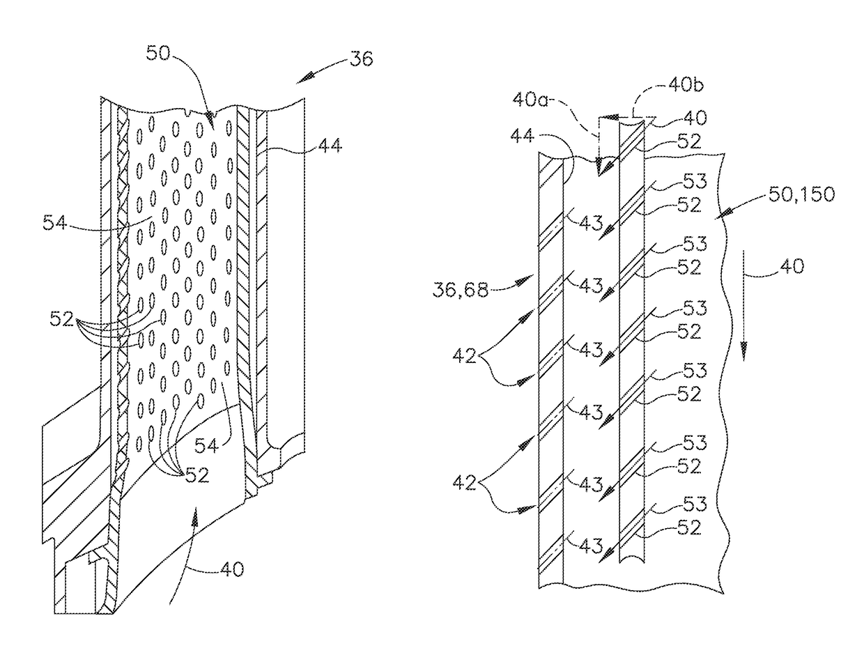
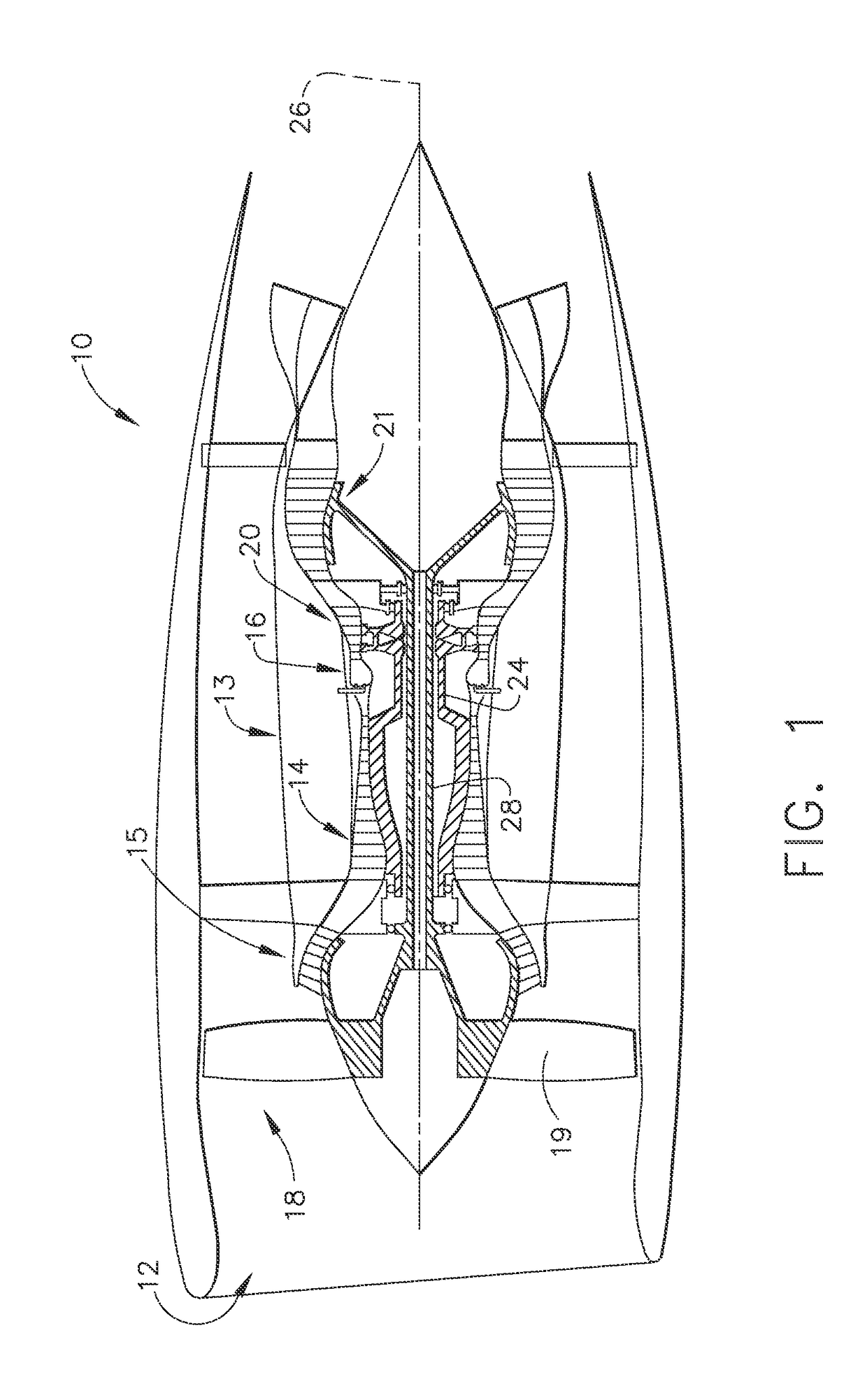
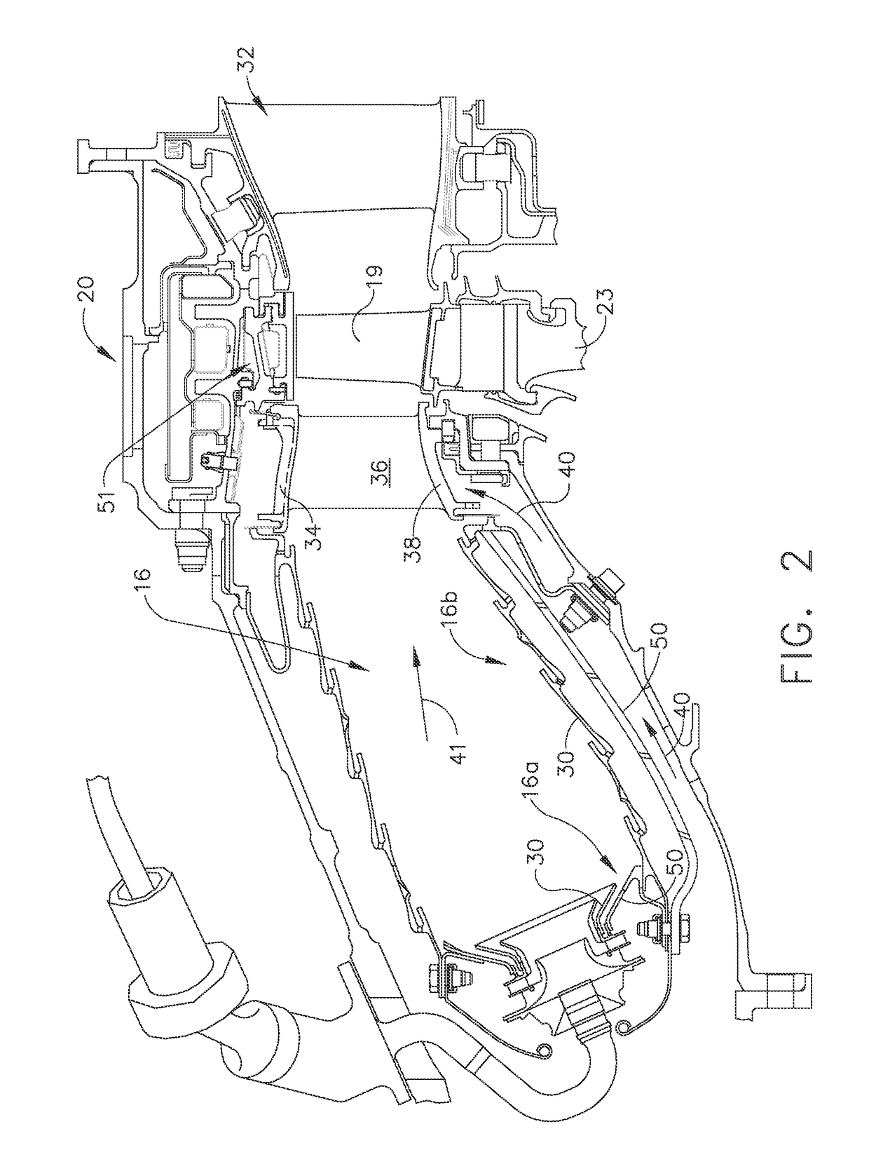
[0020]Referring now to FIGS. 1-9, various views are depicted which teach impingement inserts which reduce stagnation regions and therefore, particulate accumulation or build-up within an engine component. As a result, engine cooling may be improved. Present embodiments relate to gas turbine ...


PUM


Abstract

An engine component with particulate mitigation features is provided. The engine component comprises an internal engine component surface having a cooling flow path on one side thereof and a second component adjacent to the first component. The second component, for example an insert, may have a plurality of openings forming an array wherein the openings extend through the second component at a non-orthogonal angle to the surface of the second component.

Description

CROSS-REFERENCE TO RELATED APPLICATIONS[0001]This non-provisional application claims the benefit of priority under 35 U.S.C. § 119(e) to U.S. Provisional Patent Application No. 62 / 004,723, entitled “ANGLED IMPINGEMENT INSERT FOR PARTICULATE ACCUMULATION MITIGATION”, filed May 29, 2014, which is herein incorporated in its entirety by reference.BACKGROUND[0002]The technology described herein relates to angled impingement openings for reducing or mitigating particulate accumulation. More specifically, present embodiments relate to, without limitation, an array of openings disposed at an angle to a surface to provide angled flow and reduce particulate accumulation on part surfaces and improve cooling effectiveness.[0003]Most operating environments of a gas turbine engine receive particulate material into the engine. Such particulate can have various detrimental effects in the engine.[0004]The accumulation of dust, dirt or other particulate matter in gas turbine engines or turbo-machiner...

Claims


Application Information

Patent Timeline
Patent Type & Authority Patents(United States)
IPC IPC(8): F01D5/18F23R3/06F23R3/00F01D9/04F01D25/12F02C7/18
CPCF01D5/188F01D5/189F01D9/04F01D25/12F02C7/18F23R3/005F23R3/06F01D5/186Y02T50/676F05D2220/32F05D2240/35F05D2250/38F05D2260/201F05D2260/202F23R2900/03042F23R2900/03044Y02T50/60
Inventor BUNKER, RONALD SCOTTALLEN, JASON RANDOLPHPORTER, RYAN NICHOLASPRITCHARD, BYRON ANDREWGREENWELL, CHRISTOPHER JOSEPHSTONE, TIMOTHY DERYCKPRITCHARD, ANDREW STEPHEN
Owner GENERAL ELECTRIC CO
Why Eureka
Try Eureka