Backlight and display

a backlight and display technology, applied in the field of backlight and display, can solve the problems of display anomalies, deformation of light guide plates and display anomalies, display anomalies, etc., and achieve the effect of reducing display anomalies and preventing deformation

Active Publication Date: 2019-03-05
TRIVALE TECH LLC
View PDF8 Cites 0 Cited by
  • Summary
  • Abstract
  • Description
  • Claims
  • Application Information

AI Technical Summary

Benefits of technology

[0006]The object of the present invention is to prevent deformation in a light guide plate of a backlight and display anomalies that are caused by pressing the light guide plate with the application of compressive stress to an elastic component subject to vibrations or temperature variation in a use environment and also to reduce display anomalies caused by interference of the elastic component with the other components through movement of the elastic component.
[0008]The backlight and the display according to the present invention prevent deformation in the light guide plate and display anomalies that are caused by pressing the light guide plate with the application of compressive stress to an elastic component subject to vibrations or temperature variation in a use environment, and also reduce display anomalies caused by interference of the elastic component with the other components through movement of the elastic component.

Problems solved by technology

However, this clearance results in (i) rattle noise caused by the movement of the light guide plate in the frames and rattling of the light guide plate and the surrounding components when the vibrations or shocks are given or (ii) display anomalies caused by deviations in the optical components.
In these Japanese Patent Applications, the elastic component subject to the vibrations or the temperature variation in the use environment presses the light guide plate with the application of compressive stress, which may result in deformation of the light guide plate and display anomalies.
Moreover, the moving light guide plate interferes with the other components such as the optical sheets, which may also result in display anomalies.

Method used


Image

  • Backlight and display
  • Backlight and display
  • Backlight and display

Examples


embodiment 1

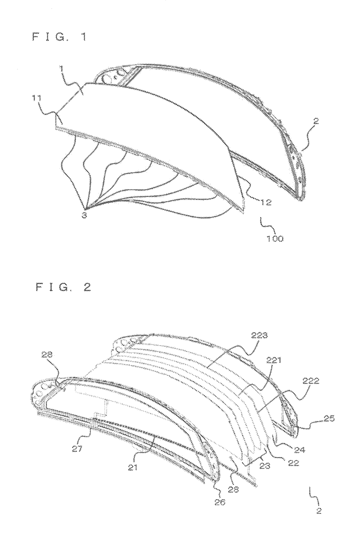
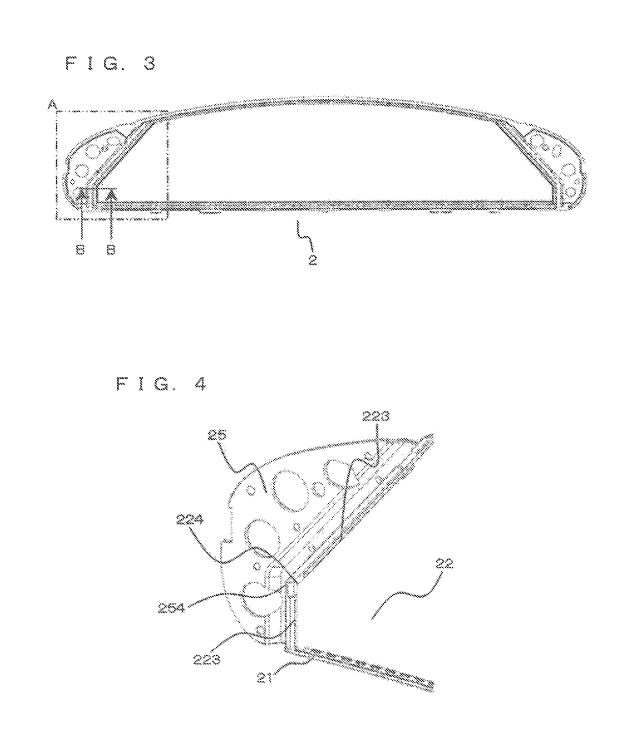
[0023]FIG. 1 is an exploded perspective view illustrating a schematic structure of a display according to the present invention. FIG. 2 is an exploded perspective view of a backlight included in the display according to the present invention.

[0024]Display

[0025]In FIG. 1 or 2, a display 100 according to the present invention includes a display panel 1 that displays an image, a backlight 2 that illuminates an opposite display surface 12 that is opposite to a display surface 11 of the display panel 1, and wiring boards 3 each for inputting a control signal to the display panel 1. The display panel 1 is, for example, a liquid-crystal display panel. The liquid-crystal display panel applies birefringence of liquid crystals, and includes (i) a first substrate obtained by forming, for example, a color layer, a light shield layer, and a counter electrode on an insulating substrate made of glass, etc., and (ii) a second substrate obtained by forming, for example, a thin film transistor functi...

embodiment 2

[0054]FIG. 10 is a cross section of the backlight 2 according to Embodiment 2 of the present invention. Although the side surface 223 of the light guide plate 22 and the side surface portion 284 of the cushion rubber 28 that faces the side surface 223 abut each other and lie in an approximately vertical plane with respect to the light emitting surface 221 in the structure of Embodiment 1, the side surface 223 of the light guide plate 22 and the side surface portion 284 of the cushion rubber 28 that faces the side surface 223 have respective sloped surfaces in Embodiment 2. As illustrated in FIG. 10, a sloped surface 2231 is formed on the side surface 223 of the light guide plate 22 that faces the cushion rubber 28. Similarly, a sloped surface 2841 is formed on the side surface portion 284 of the cushion rubber 28 that faces the light guide plate 22. When the cushion rubber 28 and the light guide plate 22 are compressively arranged according to the structure of Embodiment 2, the resp...

embodiment 3

[0055]FIG. 11 is a cross section of the backlight 2 according to Embodiment 3 of the present invention. Although the side surface 223 of the light guide plate 22 and the side surface portion 284 of the cushion rubber 28 that faces the side surface 223 abut each other and the upper surface portion 281 of the cushion rubber 28 is disposed face-to-face with the protrusion portion 264 formed on the upper frame 26 in the backlight 2 according to Embodiment 1, a step is formed in the cushion rubber 28 to fit the tip portion 2641 and a side surface portion 2642 of the protrusion portion 264 according to Embodiment 3. As illustrated in FIG. 11, a side surface 2811 forming the step of the cushion rubber 28 is formed to fit the side surface portion 2642 of the protrusion portion 264 of the upper frame 26. A planar portion 2812 is formed in the cushion rubber 28 to face the tip portion 2641 of the protrusion portion 264. Since forming the step (the side surface portion 2811 and the planar port...


PUM


Abstract

The object of the present invention is to prevent deformation in a light guide plate and display anomalies. When the light guide plate is disposed in the backlight, a cushion rubber abuts a side surface of the light guide plate and a side surface portion of a lower frame to be pressed (squeezed) into the light guide plate and the lower frame. The cushion rubber is disposed lower than the side surface of the light guide plate, and is formed at a height not interfering with optical sheets. A protrusion portion is formed from an upper surface portion of an upper frame in a space between an upper surface portion of the cushion rubber and the upper frame to face the upper surface portion of the cushion rubber.

Description

BACKGROUND OF THE INVENTIONField of the Invention[0001]The present invention relates to a backlight and a display including the backlight.Description of the Background Art[0002]Displays each include a display panel that displays an image, and a backlight that illuminates the display panel. The backlight includes a light source, a light guide plate that guides light emitted from the light source toward the display panel, optical sheets that control the light from the light guide plate, and frames holding these components. The light emitted from the light source is converted into surface light by the light guide plate, and is guided toward the display panel.[0003]The backlight has a clearance between the light guide plate and each of the frames to absorb the movement subject to vibrations in a use environment or subject to expansion and contraction of the light guide plate caused by temperature variation. However, this clearance results in (i) rattle noise caused by the movement of th...

Claims


Application Information

Patent Timeline
Patent Type & Authority Patents(United States)
IPC IPC(8): F21V8/00
CPCG02B6/0088G02B6/009G02B6/0085G02B6/0055G02B6/0051G02F1/133615G02B6/0093
Inventor ARITA, KENJI
Owner TRIVALE TECH LLC
Why Eureka
Try Eureka