Board connector

a board connector and connector technology, applied in the direction of coupling contact members, coupling device connections, coupling/insulating coupling contact members, etc., can solve the problems of inability to ensure coplanarity and electrical trouble, and achieve the effect of ensuring coplanarity with the board, improving the quality of the board connector including the terminal fitting to be mounted on the surface of the board, and reducing the risk of electrical troubl

Active Publication Date: 2019-03-05
SUMITOMO WIRING SYST LTD
View PDF12 Cites 1 Cited by
  • Summary
  • Abstract
  • Description
  • Claims
  • Application Information

AI Technical Summary

Benefits of technology

[0009]The press-fit portion is inserted into the through hole with the overlapping margin in the cross-section along the height direction in which the lead portion faces the surface of the board. Thus, a height variation of the lead portion is suppressed and coplanarity with the board is ensured. Further, the tab is inserted into the through hole without any overlapping margin in the same cross-section. Thus, a situation where the tab scrapes the inner surface of the press-fit portion is avoided and resin dregs are not produced. As a result, the quality of the board connector including the terminal fitting to be mounted on the surface of the board is improved.
[0010]An inner surface of the through hole may have two first surfaces facing each other and two second surfaces perpendicular to the first surfaces and facing each other in the cross-section. Each first surface may have a recess retracted from a contact area of the tab to be held in contact with a mating terminal fitting at a position separated from inner corners to the second surfaces, and chamfers retracted from the inner corners may be provided on outer corners on both sides across the contact area on an outer surface of the tab. When the tab passes through the through hole, the contact of the contact area of the tab with the inner surface of the through hole can be avoided by the recess of the first surface. Thus, connection reliability between the terminal fitting and the mating terminal fitting can be ensured. On the other hand, if the recess is present on the first surface of the through hole, there is a higher possibility that the outer corners of the tab contact the inner corners of the first surface to produce resin dregs. However, since the chamfers are provided on the outer corners of the tab, the contact of the outer corners of the tab with the inner corners of the first surface can be avoided and the production of resin dregs is prevented more reliably.
[0011]The press-fit portion may include cuts continuous with the chamfers, and clearances may be formed between the cuts and the inner surface of the through hole. When the press-fit portion is inserted into the through hole with the overlapping margin, resin dregs scraped by the press-fit portion may be pushed toward the housing. However, the resin dregs can be collected inside the cuts according to the above configuration, and are pushed out into the housing. In addition, since the cuts are continuous with the chamfers, the cuts and the chamfers can be processed simultaneously and manufacturing facility can be ensured.

Problems solved by technology

Thus, the tab scrapes a wall surface of the back wall in passing through the mounting hole and there has been a concern for the occurrence of an electrical trouble due to of scraped resin dregs on the printed board or the like.
Thus, so-called coplanarity cannot be ensured.

Method used


Image

  • Board connector
  • Board connector
  • Board connector

Examples


Embodiment Construction

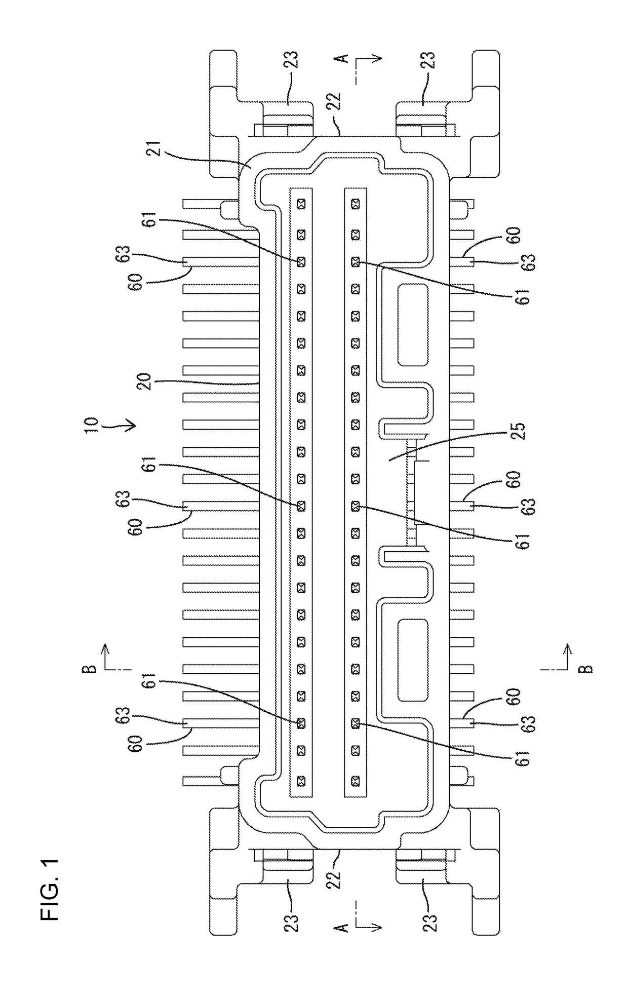
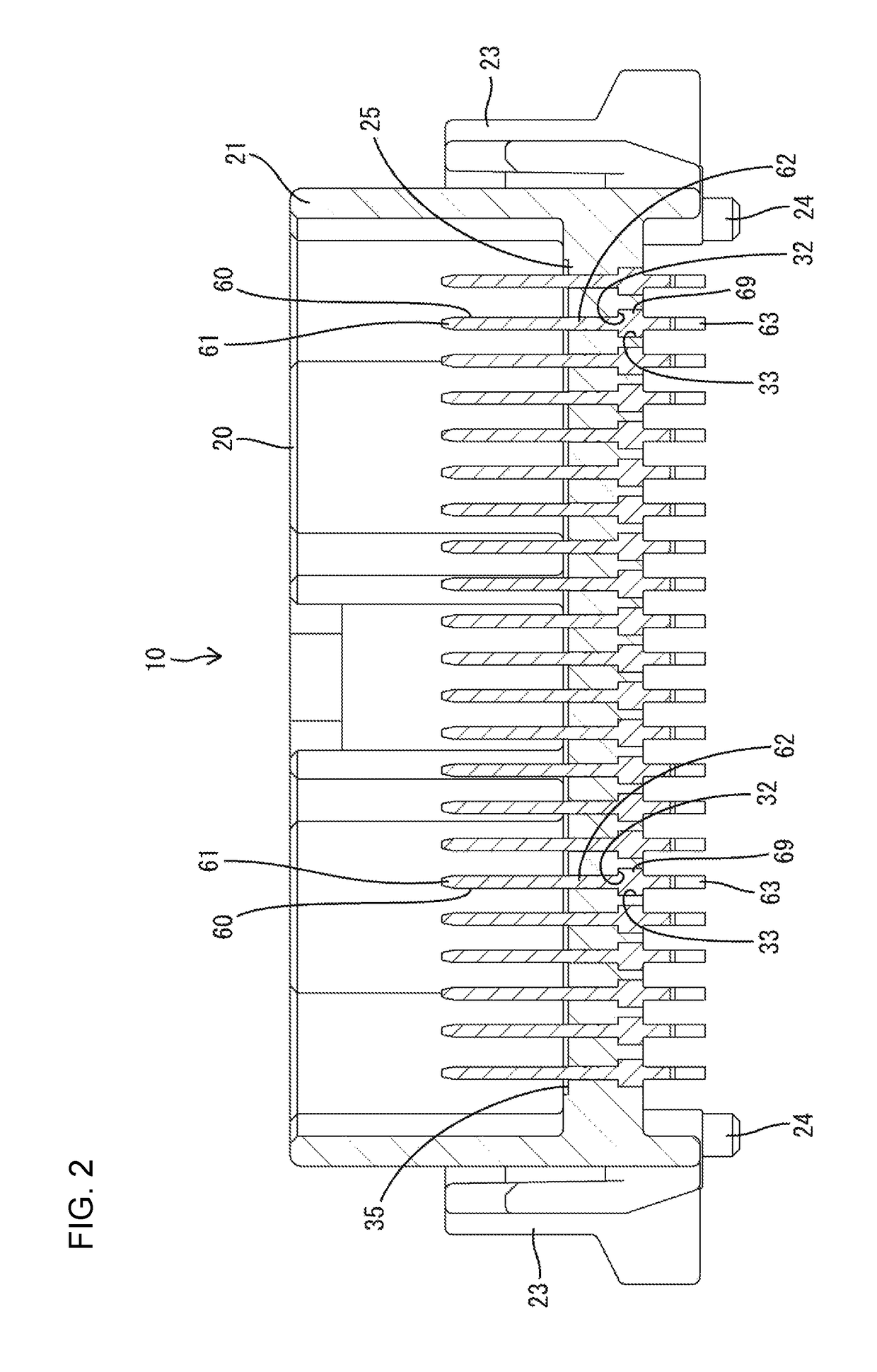
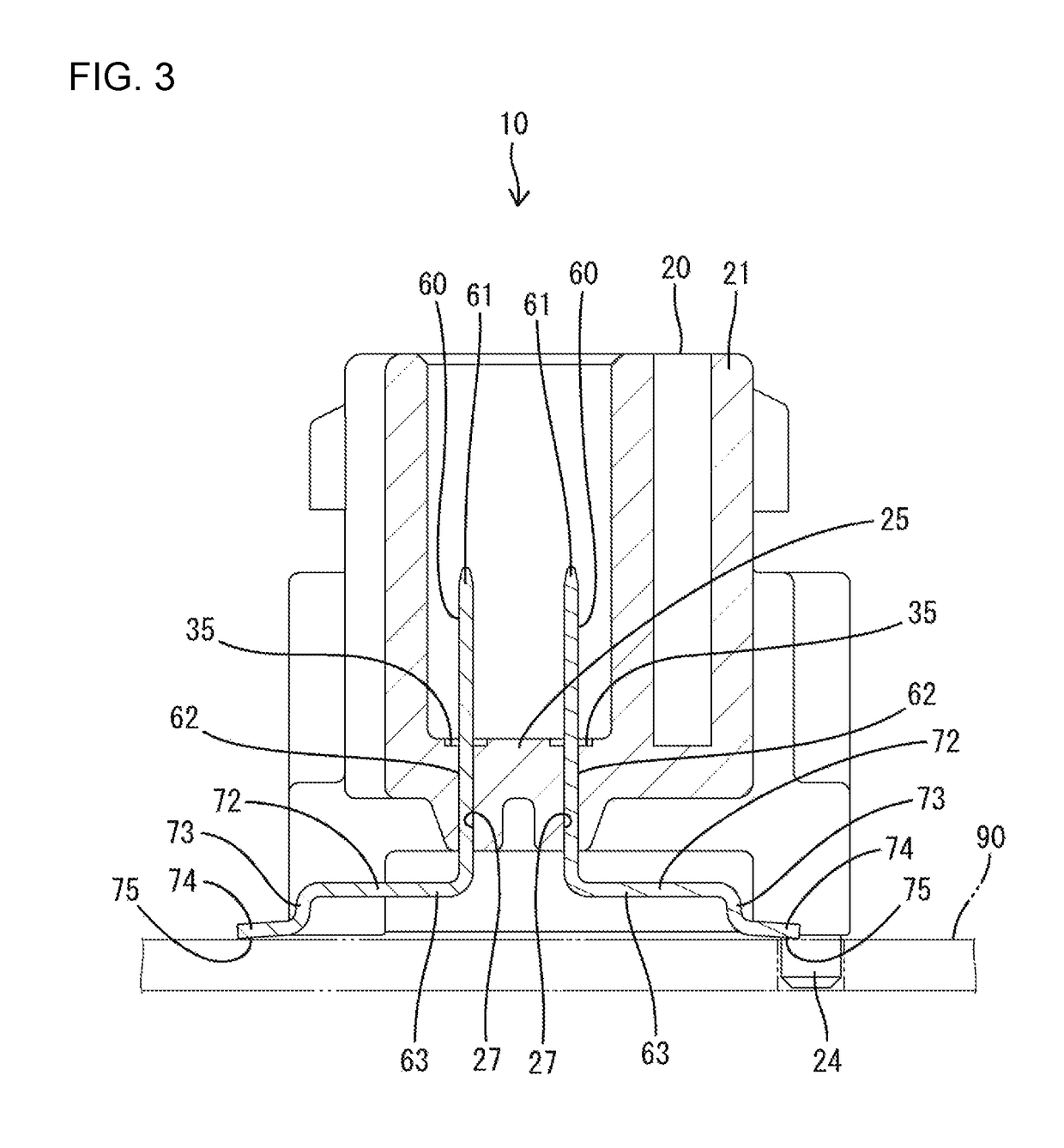
[0022]One embodiment is described with reference to the drawings. A board connector 10 according to the embodiment includes a housing 20 made of synthetic resin and terminal fittings 60 made of electrically conductive metal and to be mounted into the housing 20. The housing 20 is disposed on a printed circuit board 90 and connectable to an unillustrated mating housing. In this embodiment, a vertical connector is illustrated and is disposed on the board 90 with a connection surface of the housing 20 to the mating housing facing up (direction perpendicular to a direction of a surface of the board 90). Note that a vertical direction in the description is based on a state where the housing 20 is disposed on the board 90.

[0023]As shown in FIGS. 5 and 6, the housing 20 has a receptacle 21 in the form of a rectangular tube extending long in a lateral direction and open upward. Mounting grooves 22 are provided in the outer surfaces of both left and right end parts of the receptacle 21. Each...


PUM


Abstract

A board connector (10) has a tubular housing (20) that includes a back wall (25) with penetrating through holes (26). A terminal fitting (60) includes a tab (61) to be arranged to project into the housing (20) through the through hole (26), a press-fit portion (62) to be arranged inside the through hole (26) and a lead portion (63) to be arranged along a surface of a board (90). The press-fit portion (62) is inserted into the through hole (26) with an overlapping margin in a cross-section along a height direction in which the lead portion (63) faces the surface of the board (90). The tab (61) is inserted into the through hole (26) without any overlapping margin in the same cross-section.

Description

BACKGROUND[0001]Field of the Invention[0002]The invention relates to a board connector.[0003]Description of the Related Art[0004]Japanese Unexamined Patent Publication No. 2003-59568 discloses a receptacle-like housing to be disposed on a printed board. The housing includes a back wall through which a mounting hole portion penetrates. A terminal fitting is mounted into the housing. The terminal fitting includes a tab to be arranged inside the housing through the mounting hole, a press-fit portion to be arranged in a press-fit state in the mounting hole and a connecting end portion to be connected to the printed board. The terminal fitting is a flat rectangle having the same cross-sectional shape in a length direction.[0005]Dimensions of the outer surface of the above-described terminal fitting in a long side direction and a short side direction are equal to dimensions of the inner surface of the mounting hole in the long side direction and the short side direction. Thus, the tab scr...

Claims


Application Information

Patent Timeline
Patent Type & Authority Patents(United States)
IPC IPC(8): H01R13/41H01R12/71
CPCH01R12/716H01R13/41H01R13/02H01R13/46
Inventor KITAJIMA, MITSUNORI
Owner SUMITOMO WIRING SYST LTD
Why Eureka
Try Eureka