
Liquid ejecting apparatus

a liquid ejecting and apparatus technology, applied in the direction of power drive mechanisms, inking apparatus, printing, etc., can solve the problems of inability to position a nozzle-formed surface with high accuracy, the size of the ink jet type recording apparatus is more increased in the alignment direction of the ink jet type recording head, and the problem of inability to position a nozzle-formed surface not only in the ink jet type recording apparatus, so as to reduce the deformation of the unit base, the strength of the

Active Publication Date: 2019-03-12
SEIKO EPSON CORP
View PDF4 Cites 0 Cited by
  • Summary
  • Abstract
  • Description
  • Claims
  • Application Information

AI Technical Summary

Benefits of technology

The technical effect of this patent is that it describes a liquid ejecting apparatus with a configuration that reduces the size of the liquid ejecting heads in alignment direction. Additionally, the apparatus includes a reinforced unit base with an eave portion and side wall to increase strength and decrease deformation.

Problems solved by technology

Since the ink jet type recording head unit holds the plurality of ink jet type recording heads, it is easy to obtain a long ink jet type recording head in an alignment direction of the heads; however, as disclosed in JP-A-2015-174387, in a case where the lifting-lowering mechanisms are disposed on both sides in the alignment direction of the ink jet type recording heads, a problem arises in that the ink jet type recording apparatus is more increased in size in the alignment direction of the ink jet type recording heads.
Otherwise, as the lifting-lowering mechanism in JP-A-2015-174387, in a case where the eccentric cam provided on the apparatus main body side comes into contact with the driven cam provided on the ink jet type recording head unit side so as to be lifted and lowered, a problem arises in that it is not possible to position a nozzle-formed surface with high accuracy due to dimensional tolerance of components, positional shifts of components, or the like.
Otherwise, in a case where it is possible to lift and lower the ink jet type recording head unit with respect to a shaft, a problem arises in that the ink jet type recording head unit tilts in a direction inclined to a lifting-lowering direction with respect to the shaft, and thereby ink droplets lands at a shifted position on an ejection target medium.
Note that such problems arise not only in the ink jet type recording apparatus, but also in a liquid ejecting apparatus that ejects a liquid other than an ink.

Method used


Image

  • Liquid ejecting apparatus
  • Liquid ejecting apparatus
  • Liquid ejecting apparatus

Examples


embodiment 1

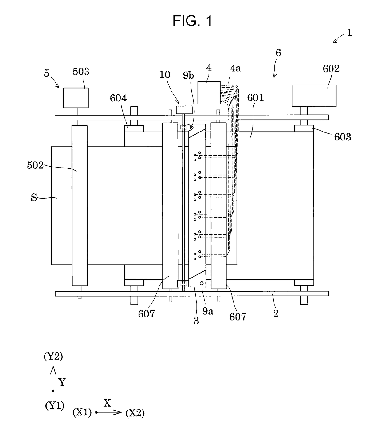
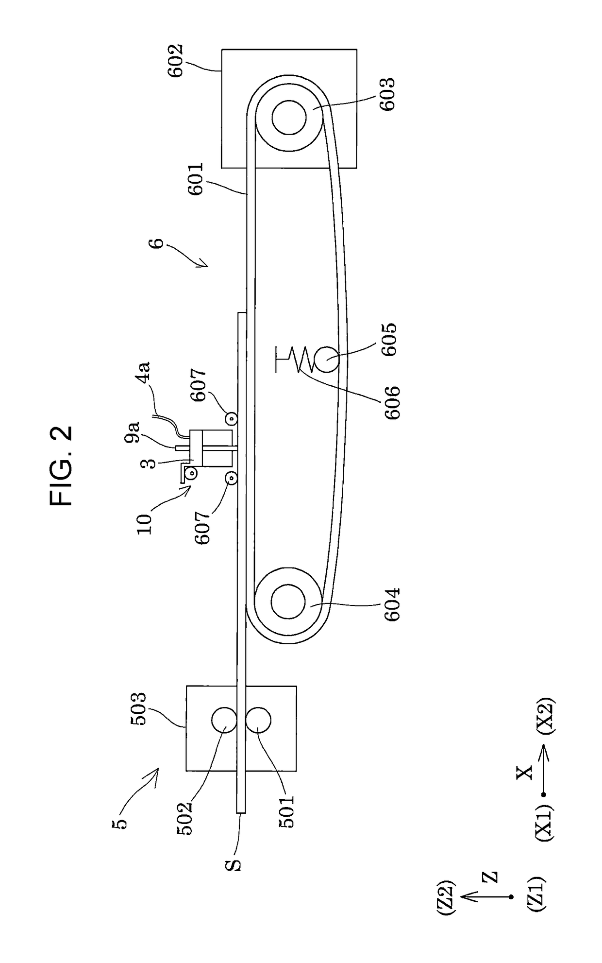
[0059]FIG. 1 is a top view illustrating a schematic configuration of an ink jet type recording apparatus as an example of a liquid ejecting apparatus according to Embodiment 1 of the invention. FIG. 2 is a side view illustrating the ink jet type recording apparatus.

[0060]As illustrated in FIGS. 1 and 2, an ink jet type recording apparatus 1 as an example of the liquid ejecting apparatus of the embodiment is a so-called line type recording apparatus 1 that transports a recording sheet S as an ejection target medium and performs printing.

[0061]Here, in the embodiment, a transport direction of the recording sheet S is referred to as a first direction X, and a direction orthogonal to the first direction X in an in-plane direction of a surface of the recording sheet S, on which an ink lands, is referred to as a second direction Y. In addition, a direction orthogonal to both of the first direction X and the second direction Y, that is, a direction orthogonal to the surface of the recordin...

embodiment 2

[0171]FIG. 20 is a front view illustrating a lifting-lowering mechanism and an ink jet type recording head unit as an example of the liquid ejecting head unit according to Embodiment 2 of the invention. FIG. 21 is a side view illustrating the ink jet type recording head unit and the lifting-lowering mechanism. Note that the same reference signs are assigned to the same members as those in the embodiment described above, and detailed description thereof is omitted.

[0172]As illustrated in FIGS. 20 and 21, the unit base 200 that configures the head unit 3 of the embodiment is provided with a lifting-lowering driven roller 240 that comes into contact with the eccentric cam 12 of the lifting-lowering mechanism 10.

[0173]In the embodiment, the lifting-lowering driven roller 240 is rotatably supported on a front end portion of the first eave portion 226a and a front end portion of the second eave portion 228a.

[0174]In the configuration, the lifting-lowering driven roller 240 comes into con...

embodiment 3

[0177]FIG. 22 is a front view illustrating a lifting-lowering mechanism and an ink jet type recording head unit as an example of the liquid ejecting head unit according to Embodiment 3 of the invention. FIG. 23 is an underside view illustrating the lifting-lowering mechanism and the ink jet type recording head unit. Note that the same reference signs are assigned to the same members as those in the embodiment described above, and detailed description thereof is omitted.

[0178]As illustrated in FIGS. 22 and 23, the unit base 200 that configures the head unit 3 of the embodiment is provided with the first contact surface 225 and the second contact surface 227, with which the lifting-lowering mechanism 10 comes into contact, on both sides of the head unit 3 in the second direction Y.

[0179]The lifting-lowering mechanism 10 comes into contact with the first contact surface 225 and the second contact surface 227. Here, the lifting-lowering mechanism 10 includes a first rotary shaft 11A, on...


PUM


Abstract

A liquid ejecting apparatus includes: an apparatus main body; a plurality of liquid ejecting heads that have a nozzle-formed surface; a unit base to which the plurality of liquid ejecting heads are fixed; and a lifting-lowering mechanism that is fixed to the apparatus main body and causes a position of the nozzle-formed surface to be shifted with respect to the apparatus main body. The lifting-lowering mechanisms are disposed in a direction orthogonal to a direction in which the plurality of liquid ejecting heads are aligned, in an in-plane direction of the nozzle-formed surface.

Description

BACKGROUND[0001]1. Technical Field[0002]The present invention relates to a liquid ejecting apparatus including a plurality of liquid ejecting heads that eject a liquid, particularly to an ink jet type recording apparatus including ink jet type recording heads that discharge an ink as the liquid.[0003]2. Related Art[0004]There is proposed an ink jet type recording head unit as an example of a liquid ejecting head unit which includes ink jet type recording heads that eject ink droplets from nozzle openings through a change in pressure by a pressure generating unit, and a head fixing substrate (unit base) on which a plurality of ink jet type recording heads adhere to a side thereof opposite to a liquid ejecting surface in which the nozzle openings are formed (for example, see JP-A-2015-174387).[0005]In such an ink jet type recording head unit, the plurality of ink jet type recording heads form a long nozzle array, thereby making it possible to increase a yield ratio and to decrease man...

Claims


Application Information

Patent Timeline
Patent Type & Authority Patents(United States)
IPC IPC(8): B41J25/308B41J25/00B41J25/316
CPCB41J25/308B41J25/001B41J25/316B41J25/3086B41J2202/21B41J2202/20
Inventor TOGASHI, ISAMU
Owner SEIKO EPSON CORP
Learn More