Antenna device and antenna manufacturing method

a technology of antenna and manufacturing method, which is applied in the direction of antenna earthing, individual entry/exit register, instruments, etc., can solve the problem that the performance of the antenna cannot be obtained as intended by the designer, and achieve the effect of reducing the loss of power supplied to the minute loop antenna

Active Publication Date: 2019-03-26
MITSUBISHI ELECTRIC CORP
View PDF38 Cites 0 Cited by
  • Summary
  • Abstract
  • Description
  • Claims
  • Application Information

AI Technical Summary

Benefits of technology

[0013]In the present invention, since the minute loop antenna is mounted on the circuit board such that: the loop surface is perpendicular to the plane on which the circuit pattern is formed; and the normal line passing though the loop surface does not pass through the circuit pattern, a magnetic current is not hindered by the circuit pattern, and loss of the power supplied to the minute loop antenna can be reduced.

Problems solved by technology

Thus, there is a problem that antenna performance cannot be obtained as intended by the designer.

Method used


Image

  • Antenna device and antenna manufacturing method
  • Antenna device and antenna manufacturing method
  • Antenna device and antenna manufacturing method

Examples


embodiment 1

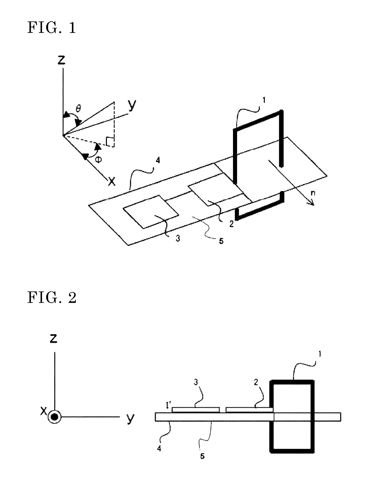
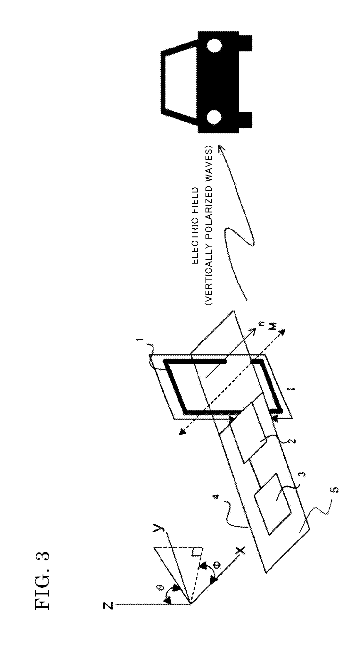
[0050]Hereinafter, an antenna device according to Embodiment 1 will be described with reference to FIGS. 1 to 9. FIG. 1 is a perspective view of the antenna device according to Embodiment 1. In FIG. 1, the antenna device includes a minute loop antenna element 1 (minute loop antenna 1), a transmitting circuit 2 (feeder circuit 2), a switch 3, a circuit board 4, and a ground 5. In the following description, as expression of a spherical coordinate system, the direction of an angle formed with a Z axis is denoted by θ, and the direction of an angle formed with an X axis is denoted by ϕ.

[0051]When power is supplied to the minute loop antenna 1, the minute loop antenna 1 emits radio waves. The minute loop antenna 1 is a conductor formed in a loop shape and has two terminals (hereinafter, referred to as end portions). The shape of the minute loop antenna 1 according to the present embodiment is a quadrangular shape as shown in FIG. 1, but is not limited thereto, and may not be a symmetrica...

embodiment 2

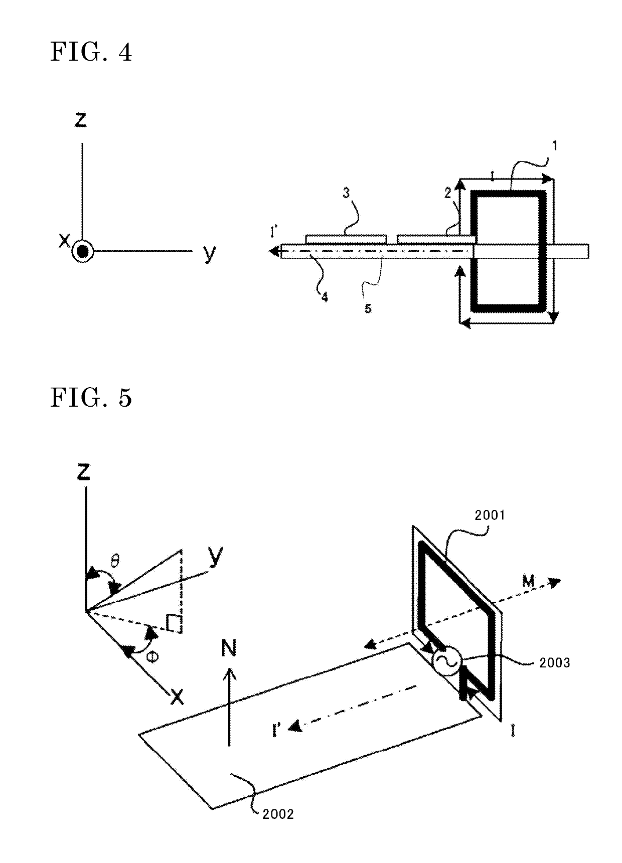
[0070]Hereinafter, an antenna device according to Embodiment 2 will be described. The antenna device according to Embodiment 2 is characterized in that the shape of the minute loop antenna 1 is symmetrized.

[0071]The minute loop antenna 1 according to the present embodiment is characterized in that the shape of the minute loop antenna 1 above the plane (XY plane) of the circuit board 4 and the shape of the minute loop antenna 1 below the plane (XY plane) of the circuit board 4 are symmetrical to each other.

[0072]In general, it is well known that when the shape of the minute loop antenna 1 (including the ground 5) is symmetrized based on the feeding point of the minute loop antenna 1 mounted on the circuit board 4, the proportion of the dipole mode electric current I′ in all electric currents supplied from the feeding point becomes low. That is, in the case of the antenna device shown in Embodiment 1, by making the structure of the minute loop antenna 1 symmetrical with respect to the...

embodiment 3

[0074]Hereinafter, an antenna device according to Embodiment 3 will be described with reference to FIG. 10. The antenna device according to Embodiment 3 is characterized in that the minute loop antenna 1 is composed of two conductors. In the description of each component shown in FIG. 10, the components that are the same as those shown in FIGS. 1 to 4 and 9 are designated by the same numerals, and the description thereof is omitted.

[0075]FIG. 10 is a side view of the antenna device according to Embodiment 3. In FIG. 10, the minute loop antenna 1 includes a first conductor 101, a second conductor 102, and a connection portion 103. The first conductor 101 has a shape obtained by bending a conductor rod, and is electrically connected at one end thereof to the feeder circuit 2 and electrically connected at another end thereof to the connection portion 103. The second conductor 102 has a shape obtained by bending a conductor rod, and is electrically connected at one end thereof to the gr...


PUM


Abstract

The present invention is characterized by an antenna device including: a circuit board; a circuit pattern formed by a conductor on a surface of the circuit board; and a minute loop antenna mounted on the circuit board and formed in a loop shape by a conductor having two end portions, wherein the circuit pattern includes at least a feeder circuit configured to supply power to the minute loop antenna, and a ground, and the minute loop antenna is mounted on the circuit board such that: the conductor having the two end portions is connected at one end thereof to the feeder circuit and connected at another end thereof to the ground; a loop surface of the conductor having the two end portions is perpendicular to a plane on which the circuit pattern is formed; and a normal line passing through the loop surface does not pass through the circuit pattern.

Description

CROSS REFERENCE TO RELATED APPLICATIONS[0001]This application is a National Stage of International Application No. PCT / JP2014 / 004060 filed Aug. 4, 2014, claiming priority based on Japanese Patent Application No. PCT / JP2014 / 002192 filed Apr. 17, 2014, the contents of all of which are incorporated herein by reference in their entirety.TECHNICAL FIELD[0002]The present invention relates to an antenna device mounted in a remote keyless entry system and a manufacturing method for the antenna device.BACKGROUND ART[0003]Hitherto, a remote keyless entry system has been developed which performs wireless communication via radio waves between a vehicle and a portable apparatus carried by a user of the vehicle to allow the doors of the vehicle to be locked or unlocked.[0004]The remote keyless entry system includes: the portable apparatus that emits radio waves for instructing locking or unlocking of the doors by an operation of the user; and an on-vehicle apparatus that locks or unlocks the door...

Claims


Application Information

Patent Timeline
Patent Type & Authority Patents(United States)
IPC IPC(8): H01Q1/24H01Q1/32H01Q1/38H01Q1/42H01Q1/48H01Q7/00G07C9/00
CPCH01Q1/24H01Q1/3241H01Q1/38H01Q1/48H01Q7/00H01Q7/005H01Q1/42G07C2009/00753G07C2009/00968
Inventor MAKIMURA, HIDETOSHINISHIMOTO, KENGOFUKASAWA, TORUTAKAHASHI, KAZUNORIHOJO, KAZUYA
Owner MITSUBISHI ELECTRIC CORP
Why Eureka
Try Eureka