Printing apparatus

a technology of printing apparatus and printing plate, which is applied in the field of printing plate, can solve problems such as damage to the medium, and achieve the effect of reducing the useless consumption of electric power

Active Publication Date: 2019-04-02
SEIKO EPSON CORP
View PDF8 Cites 3 Cited by
  • Summary
  • Abstract
  • Description
  • Claims
  • Application Information

AI Technical Summary

Benefits of technology

[0010]A printing apparatus according to the invention includes a transport unit that transports a medium to a support table that supports the medium, a printing unit that is provided at a position facing the support table and that performs printing by depositing a liquid to the medium on the support table, and a drying unit that dries the liquid deposited on the medium. The drying unit includes a first heater unit capable of heating a printed side surface of the medium that has been subjected to be printing and a second heater unit capable of heating an opposite side surface of the medium to the printed side surface. The first heater unit includes a plurality of first heaters that are disposed at the same position in a transport direction of the medium and that are arranged in a direction orthogonal to the transport direction. Each of the first heaters includes a first heating element that heats the medium. The second heater unit includes at least one second heater that is disposed at a position superposed on the first heater unit in the transport direction and that is disposed at a position between adjacent first heating elements of the first heating elements in the direction orthogonal to the transport direction.
[0011]In this construction, since the plurality of first heaters and the at last one second heater are all disposed at the same position in the transport direction, the distances between the first heaters and the printing unit and the distance between the at least one second heater and the printing unit are equal to each other. Therefore, when a medium having been subjected to printing is transported to the drying unit, the printed medium can be heated in such a manner that the amount of time from the printing on the medium to the heating of the medium varies to a reduced degree or substantially does not vary from one portion of the medium to another.
[0012]The foregoing printing apparatus may further include a first control unit that generates a control signal that controls an operation of the printing apparatus, a plurality of second control units that control a state of supply of electric current to the first heaters and a state of supply of electric current to the at least one second heater on the basis of the control signal transmitted from the first control unit, and a control signal transmission path through which the control signal is transmitted from the first control unit to the second control units. The first control unit and the plurality of second control units may be connected in a parallel manner via the control signal transmission path.
[0013]This construction allows the electrical connecting construction of the first control unit and the second control units to be simplified in comparison with a construction in which a first control unit is connected to each of second control units separately via a plurality of control signal transmission paths that are parallel to each other and that are provided separately for each second control unit.
[0014]Furthermore, in the foregoing printing apparatus, the first heaters may be individually controllable.
[0015]According to this construction, useless consumption of electric power can be reduced by, for example, performing such a control as to supply electric power only to first heaters that face a medium according to the width of the medium, that is, the dimension of the medium in a direction that intersects the transport direction.

Problems solved by technology

As a result, the drying of the ink on the sheet of paper MR may become uneven or the shrinkage of the sheet of paper MR due to the ink deposited thereon may occur to varying degrees and therefore lead to damage to the medium.

Method used


Image

  • Printing apparatus
  • Printing apparatus
  • Printing apparatus

Examples


Embodiment Construction

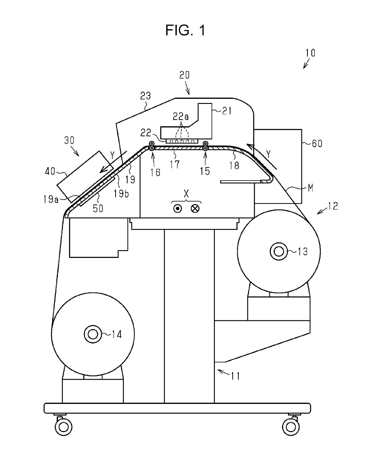
[0043]An exemplary embodiment of the printing apparatus of the invention will be described hereinafter with reference to the accompanying drawings. In the following exemplary embodiment, the printing apparatus is an ink jet type printer that forms characters, images, etc. on a continuous sheet of paper as an example of a medium by discharging an ink as an example of a liquid to the continuous sheet. The ink in the exemplary embodiment is an aqueous resin ink that contains water as a solvent and that contains as a solute a pigment made of a resin.

[0044]As shown in FIG. 1, a printing apparatus 10 includes a body frame 11. The body frame 11 includes a transport unit 12 that transports a continuous sheet of paper M along a transport path from an upstream side to a downstream side in a roll-to-roll method, a support table 17 that supports the continuous sheet M from below at an intermediate position on a transport path, and a printing unit 20 that performs printing on the continuous shee...


PUM


Abstract

A printing apparatus includes a transport unit for transporting a continuous sheet, a printing unit for printing by discharging ink to the continuous sheet, and a drying unit for drying the ink deposited on the continuous sheet. The drying unit includes a first heater unit for heating a printed surface of the continuous sheet and a second heater unit for heating the opposite surface of the continuous sheet to the printed surface. The first heater unit includes a plurality of first heaters that are disposed at the same position in a transport direction and that are arranged in width directions. The second heater unit includes a plurality of second heaters that are disposed at a position superposed on the first heater unit in the transport direction and that are disposed at positions between adjacent ones of first heating elements of the first heaters in the width directions.

Description

BACKGROUND[0001]1. Technical Field[0002]The present invention relates to a printing apparatus, such as an ink jet type printer, that performs printing on a medium, for example, by discharging a liquid onto the medium transported onto a support table that supports the medium.[0003]2. Related Art[0004]A known example of this type of printing apparatus is a so-called hot-melt type printing apparatus (see, e.g., JP-A-11-115175) that, after depositing an ink that is an example of a liquid that is heated to melt and then solidifies onto a sheet of paper that is an example of a medium, heats the surface of the sheet of paper on which the liquid has been deposited so as to fix the ink to the sheet of paper. Such a printing apparatus has at a position above the sheet of paper a heater for fixing the ink.[0005]It is preferable that this heater be provided as a common component part for a plurality of kinds of printing apparatuses that vary in the maximum width of paper that the apparatuses ca...

Claims


Application Information

Patent Timeline
Patent Type & Authority Patents(United States)
IPC IPC(8): B41J11/00B41M7/00B41J2/42G03G13/20
CPCB41J11/002B41M7/00G03G13/20B41J2/42B41J11/00212B41J11/00216B41J11/0024
Inventor NAKANO, SHUICHIRO
Owner SEIKO EPSON CORP
Why Eureka
Try Eureka