
Illumination device for a liquid crystal display

Active Publication Date: 2019-04-09
COVESTRO DEUTSCHLAND AG
View PDF10 Cites 0 Cited by
  • Summary
  • Abstract
  • Description
  • Claims
  • Application Information

AI Technical Summary

Benefits of technology

The invention is a lighting system for displaying pictures on liquid-crystal displays. The system is designed to be thin and use less energy than previous systems. It also improves the quality of the displayed pictures.

Problems solved by technology

Disadvantages of direct lighting are the high costs and the energy consumption, since it is necessary to have a multiplicity of light sources.
Corresponding formed displays, however, have only reduced representation qualities.
Although, by this prior art, the layer thickness of the illumination apparatus can be reduced and the energy consumption can simultaneously be reduced, a problem with this prior art is that the light coupled out is directional and emitted in a direction parallel to the surface normal of the light guide substrate.
This entails the problem that the illumination apparatus has different brightnesses for an observer's eyes.
This leads to a liquid-crystal display having reduced representation qualities.

Method used


Image

  • Illumination device for a liquid crystal display
  • Illumination device for a liquid crystal display
  • Illumination device for a liquid crystal display

Examples


Embodiment Construction

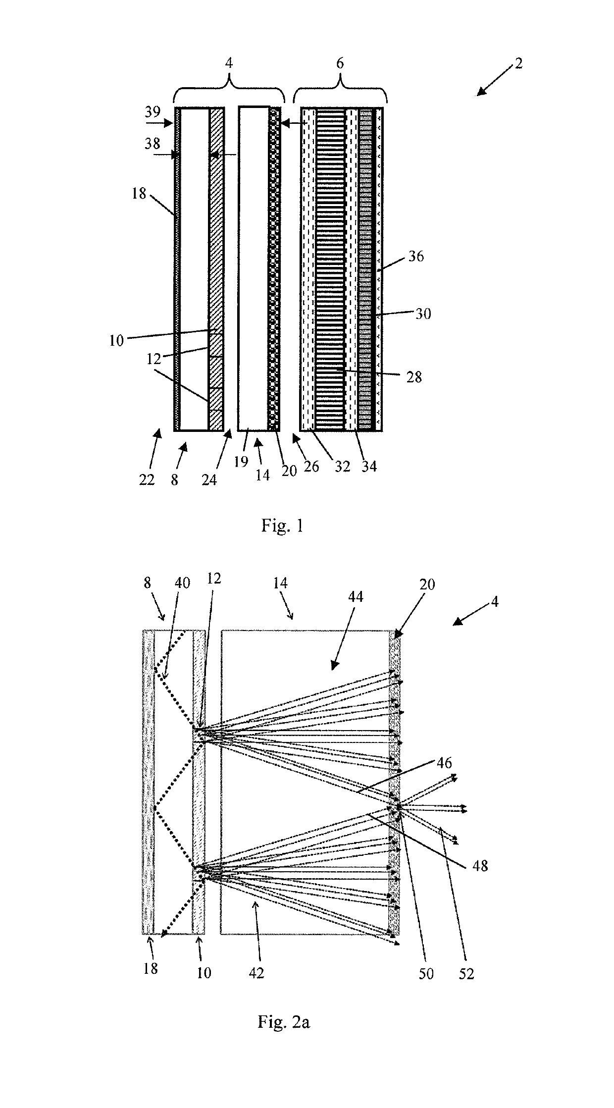
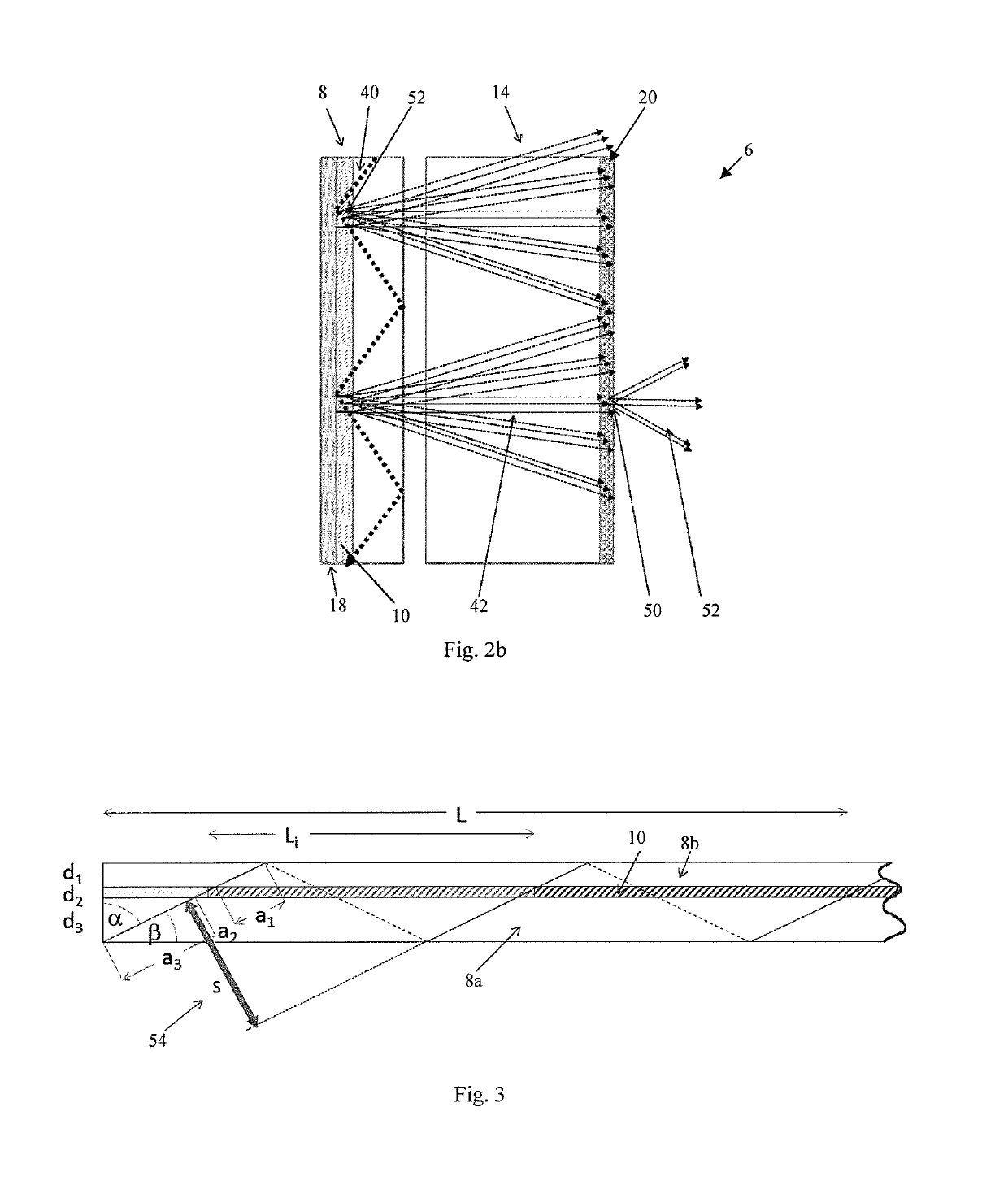
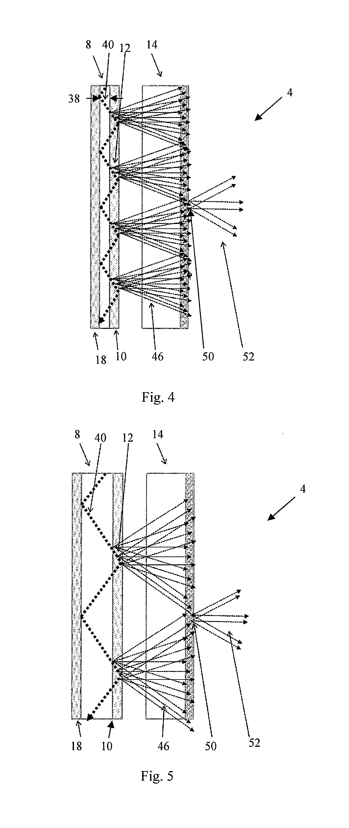
[0018]The illumination apparatus comprises a light guide substrate. The light guide substrate, also referred to as a waveguide, is adapted in order to guide at least one directional light beam, preferably a laser beam. The directional light beam can be coupled or shone in on one edge of the light guide substrate. In particular, the light beam is shone in with a predeterminable input angle. The directional light beam can propagate through the light guide substrate by total reflection at the interfaces of the light guide substrate, or of the holographic-optical output coupling substrate which is in optical contact with the light guide substrate. It is to be understood that a multiplicity of directional light beams may be coupled in on an edge, as will be explained below.

[0019]Furthermore, a holographic-optical output coupling substrate is provided, which is in direct optical contact with the light guide substrate. For example, the light guide substrate may comprise the holographic-opt...


PUM


Abstract

The invention relates to an illumination device for illuminating at least one light modulator system of a liquid crystal display, the device comprising at least one waveguide substrate for guiding at least one targeted light beam that can be coupled into the waveguide substrate. The waveguide substrate is at least in optical contact with at least one holographic optical decoupling substrate comprising a plurality of decoupling regions and a decoupling region is at least designed to decouple part of the targeted light beam in the form of a plurality of sub-beams in the direction of the light modulator system. At least one diffuser module is provided, said diffuser module being designed in such a way that at least the outermost sub-beams of two neighboring decoupling regions are at least adjacent to one another before exiting the diffuser module.

Description

CROSS REFERENCE TO RELATED APPLICATIONS[0001]This application is a § 371 National Stage Application of PCT / EP2013 / 066686, filed Aug. 9, 2013, which claims priority to EP 12180244.1, filed Aug. 13, 2012.BACKGROUNDField of the Invention[0002]The invention relates to an illumination apparatus for illuminating at least one light modulator device of a liquid-crystal display, comprising at least one light guide substrate for guiding at least one directional light beam which can be coupled into the light guide substrate, the light guide substrate being at least in optical contact with at least one holographic-optical output coupling substrate comprising a multiplicity of output coupling regions, an output coupling region being at least adapted in order to couple out a part of the directional light beam in the form of a multiplicity of subbeams in the direction of the light modulator device. The invention furthermore relates to an illumination system and to a liquid-crystal display.Descript...

Claims


Application Information

Patent Timeline
IPC IPC(8): F21V8/00G02F1/1335G03H1/30G03H1/22
CPCG02B6/0051G02B6/005G02B6/0035G02F1/133617G02B6/0028G03H2240/55G03H1/30G03H2001/2226G03H2001/2231G03H2001/2234G02B6/0061
Inventor FACKE, THOMASBRUDER, FRIEDRICH-KARLHAGEN, RAINERWALZE, GUNTHERROELLE, THOMASBERNETH, HORSTHONEL, DENNISWEISER, MARC-STEPHANHOHEISEL, WERNER
Owner COVESTRO DEUTSCHLAND AG
Learn More