
Through-hole electrode substrate and semiconductor device using through-hole electrode substrate

a technology of electrode substrate and semiconductor device, which is applied in the direction of resist details, printed circuit aspects, non-metallic protective coating applications, etc., can solve the problems of gap generation and defects such as dropout of filler

Active Publication Date: 2019-04-09
DAI NIPPON PRINTING CO LTD
View PDF65 Cites 5 Cited by
  • Summary
  • Abstract
  • Description
  • Claims
  • Application Information

AI Technical Summary

Benefits of technology

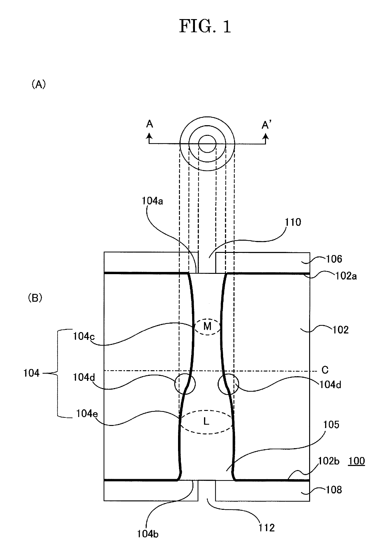
[0052]In addition, in the through-hole electrode substrate 100 of the embodiment of the invention related to the present embodiment, as described above, at least one of the insulation layers (gas discharge member) 106 and 108 is arranged so as to contact with the filler 105 exposed to the first surface 102a and second surface 102b of the substrate 102. Therefore, it is possible for the insulation layer (gas discharge member) 106 and / or 108 to discharge gas generated and discharged within the through-hole 104 to the exterior, remove defects caused by accumulated gas in a gas reservoir within the through-hole 104, it is possible to prevent the filler 105 from dropping out from the through-hole 104, and it is possible to provide a through-hole electrode substrate with a high level of reliability.

Problems solved by technology

However, even when attempting to prevent dropout of the filler by such a technique, a gap is generated between the filler and the side wall of the through-hole and a gas reservoir may be generated.
When heat is applied to the substrate in this state, in the prior art there is a possibility that gas which has collected into a gas reservoir expands causing destruction of the through-hole or filler which causes defects such as dropout of the filler.

Method used


Image

  • Through-hole electrode substrate and semiconductor device using through-hole electrode substrate
  • Through-hole electrode substrate and semiconductor device using through-hole electrode substrate
  • Through-hole electrode substrate and semiconductor device using through-hole electrode substrate

Examples


first embodiment

[0043]The structure of a through-hole electrode substrate 100 of the embodiment of the invention related to the present embodiment is explained while referring to FIG. 1. FIG. 1 (A) is a planar diagram of the through-hole electrode substrate 100 of the embodiment of the invention related to the present embodiment seen from the upper surface. FIG. 1 (B) is a cross-sectional diagram of the line A˜A′ in FIG. 1 (A). Both FIGS. 1 (A) and (B) show a part of the through-hole electrode substrate 100 of the embodiment of the invention related to the present embodiment for the convenience of explanation.

[0044]The through-hole electrode substrate 100 of the embodiment of the invention related to the present embodiment is arranged with a substrate 102, a through-hole 104, a filler 105, insulation layers 106 and 108, and via's 110 and 112. Furthermore, a wiring structure body and electronic components and the like may also be further mounted respectively on a first surface 102a and second surfac...

second embodiment

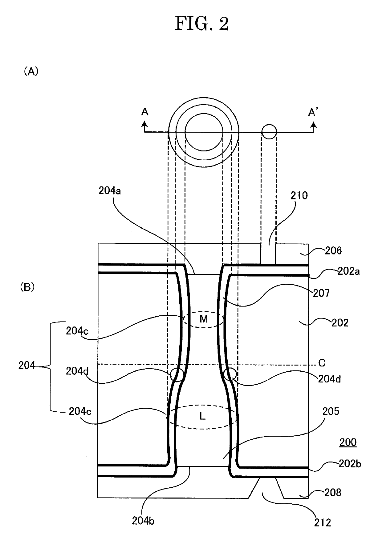
[0054]The structure of a through-hole electrode substrate 200 of the embodiment of the invention related to the present embodiment is explained while referring to FIG. 2. FIG. 2 (A) is a planar diagram of the through-hole electrode substrate 200 of the embodiment of the invention related to the present embodiment seen from the upper surface. FIG. 2 (B) is a cross-sectional diagram of the line A˜A′ in FIG. 2 (A). Both FIGS. 2 (A) and (B) show a part of the through-hole electrode substrate 200 of the embodiment of the invention related to the present embodiment for the convenience of explanation.

[0055]The through-hole electrode substrate 200 of the embodiment of the invention related to the present embodiment is arranged with a substrate 202, a through-hole 204, a filler 205, insulation layers 206 and 208, and via's 210 and 212. Furthermore, a wiring structure body and electronic components and the like may also be further mounted respectively on a first surface 202a and second surfac...

third embodiment

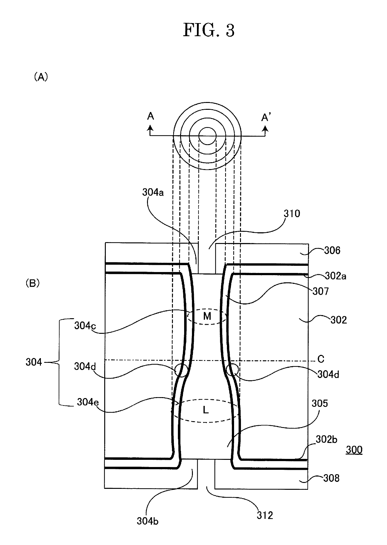
[0065]The structure of a through-hole electrode substrate 300 of the embodiment of the invention related to the present embodiment is explained while referring to FIG. 3. FIG. 3 (A) is a planar diagram of the through-hole electrode substrate 300 of the embodiment of the invention related to the present embodiment seen from the upper surface. FIG. 3 (B) is a cross-sectional diagram of the line A˜A′ in FIG. 3 (A). Both FIGS. 3 (A) and (B) show a part of the through-hole electrode substrate 300 of the embodiment of the invention related to the present embodiment for the convenience of explanation.

[0066]The through-hole electrode substrate 300 of the embodiment of the invention related to the present embodiment is arranged with a substrate 302, a through-hole 304, a filler 305, insulation layers 306 and 308, and via's 310 and 312. Furthermore, a wiring structure body and electronic components and the like may also be further mounted respectively on a first surface 302a and second surfac...


PUM


Abstract

A through-hole electrode substrate includes a substrate including a through-hole extending from a first aperture of a first surface to a second aperture of a second surface, an area of the second aperture 5 being larger than that of the first aperture, the through-hole having a minimum aperture part between the first aperture and the second aperture, wherein an area of the minimum aperture part in a planar view is smallest among a plurality of areas of the through-hole in a planar view, a filler arranged within the 10 through-hole, and at least one gas discharge member contacting the filler exposed to one of the first surface and the second surface.

Description

CROSS-REFERENCE TO RELATED APPLICATIONS[0001]This application is based upon and claims the benefit of priority from the prior Japanese Patent Application No. 2013-241392, filed on Nov. 21, 2013, and PCT Application No. PCT / JP2014 / 080649, filed on Nov. 19, 2014, the entire contents of which are incorporated herein by reference.FIELD[0002]The embodiment of the invention is related to a through-hole electrode substrate arranged with a through-hole electrode which passes through a top surface and rear surface of a substrate. In particular, the embodiment of the invention is related to a through-hole electrode substrate used as an interposer substrate for connecting a plurality of elements. In addition, the embodiment of the invention is related to a semiconductor device which uses the through-hole electrode substrate.BACKGROUND[0003]In recent years, the development of through-hole electrode substrates arranged with a conductive part which conducts a top surface and rear surface of a sub...

Claims


Application Information

Patent Timeline
Patent Type & Authority Patents(United States)
IPC IPC(8): H01L23/498H05K1/11H01L25/065H05K3/28H05K3/44H01L23/48H01L25/18H01L23/13H01L23/15
CPCH01L23/49827H01L23/481H01L23/49894H01L25/065H01L25/18H05K1/115H05K3/28H05K3/445H05K2203/0594H01L23/13H01L23/15H01L2224/0401H01L2224/04042H01L2224/16145H01L2224/48091H01L2224/73257H01L2225/0651H01L2225/06517H01L2225/06572H01L2924/14H01L2924/1432H01L2924/1434H01L2924/1461H05K2201/0959H05K2201/09154H05K2201/09563H05K2201/09581H05K2201/09854H01L2924/00014H01L2224/16165H01L24/13H01L24/16H01L24/29H01L24/32H01L24/48H01L24/73H01L2224/13109H01L2224/13144H01L2224/13147H01L2224/16146H01L2224/16227H01L2224/2919H01L2224/32225H01L2224/48227H01L2224/81805H01L2224/8385H01L2924/15787H01L2924/15788H01L2924/1579H01L2924/381H01L2924/05432H01L2924/0665H01L2924/07025
Inventor KURAMOCHI, SATORUKOIWA, SUMIOYOSHIOKA, HIDENORI
Owner DAI NIPPON PRINTING CO LTD
Learn More