Swivel assemblies

a technology of swivel assemblies and swivel rods, which is applied in the direction of swivels, fastening means, safety belts, etc., can solve the problems of insufficient size of through holes, which is typically, but not necessarily, of insufficient size, and achieve the effect of reducing twisting loads

Active Publication Date: 2019-04-30
TREEMAGINEERS
View PDF31 Cites 3 Cited by
  • Summary
  • Abstract
  • Description
  • Claims
  • Application Information

AI Technical Summary

Benefits of technology

[0009]This arrangement means that no component has to be inserted into the second component other than through a face directed to the first component, thereby removing the need to provide sufficient axial dimension to accommodate assembly of the swivel, as is the case of known proposals.
[0013]Typically, a compressive thrust bearing is located between the first and second components to react forces that compress the components together along the axis. To minimise axial length of the swivel, the compressive thrust bearing may be constituted by a washer disposed between the components.
[0017]Since the bearing is inserted into a recess of the second component that faces the first component, access is required only to that face of the second component in which the recess is formed. This facilitates the construction of swivel connections to a wider range of components and structures than would be possible using conventional construction arrangements.

Problems solved by technology

In the latter case, the through hole is typically, but not necessarily, of insufficient size to allow the bearing to pass through it.

Method used


Image

  • Swivel assemblies
  • Swivel assemblies
  • Swivel assemblies

Examples


Embodiment Construction

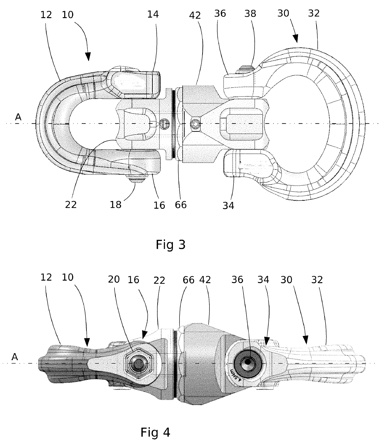
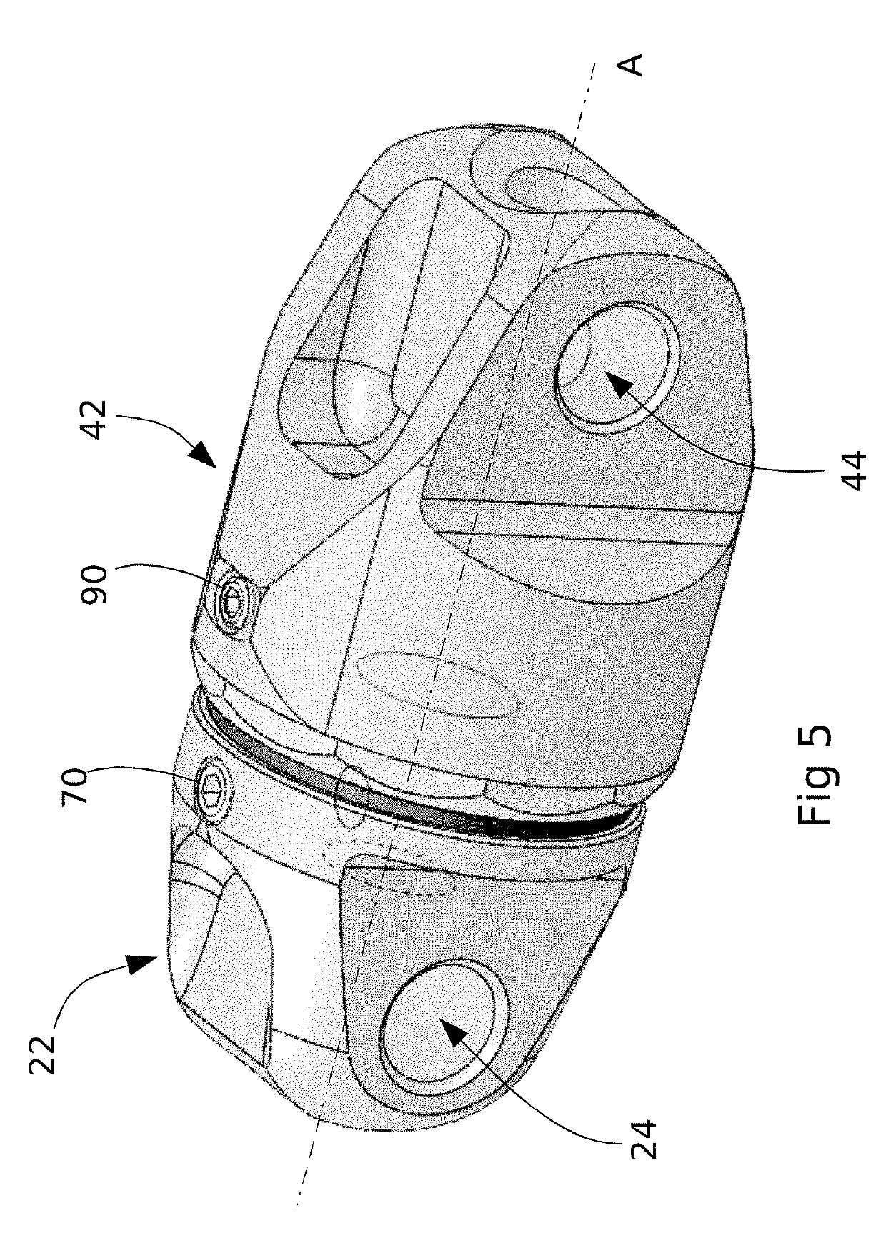
[0033]With reference to FIGS. 3 and 4, a first embodiment of the invention provides a swivel that has two interconnected shackle sub-assemblies 10; 30. The sub-assemblies 10; 30 are free to rotate with respect to one another about a pivot axis A.

[0034]Each shackle sub-assembly 10; 30 includes a shackle loop 32; 12 that extends in a U-shaped or C-shaped profile, each having first and second attachment portions 14, 16; 34; 36. The attachment portions 14, 16; 34; 36 have flat surfaces that are parallel to and face one another. Each shackle has respective coaxial bores formed through its attachment portions 14, 16; 34; 36. The bore of each of the first attachment portions 14; 34 is counterbored and the bore of each of the second attachment portions 16; 36 is formed with a recess of hexagonal cross-section. Each shackle sub-assembly further includes a respective axle bolt. The bolt has a head that has a cylindrical periphery and a recessed hexagonal drive socket 36 (just one being visibl...


PUM


Abstract

A swivel assembly is disclosed that allows first and second sub-assemblies to swivel with respect to one another. The assembly comprises a first component and a second component, at least one having a connection formation for connection to another object. An interconnection assembly interconnects the components such that they are free to rotate about an axis. The interconnection assembly comprises an axle secured for free rotation about the axis within a recess of the second component. The axle is retained within the recess by a bearing secured within the recess by a cap located in an opening of the recess that is directed towards the first component, the axle extending through the cap along the axis for connection with the first component.

Description

BACKGROUND TO THE INVENTION[0001]Field of the Invention[0002]This invention relates to swivel assemblies and to swivels.[0003]Summary of the Prior Art[0004]A swivel is an anti-torsion device for reducing the twisting loads within climbing and hauling lines. Traditionally, these have constituted of an assembly that includes pair of swivel bodies with a thrust or roller bearing joining the two bosses to enable them to spin independently.[0005]Swivels come in a range of sizes, shapes and connection arrangements. An assembly that constitutes a swivel may typically have two swivel eyes or one swivel eye and a boss or two bosses. In general, an eye is used to connect the swivel to a carabiner and a boss is used to connect the swivel to a flexible line, lanyard or shackle.[0006]It is desirable that the swivel and shackle body be as short as possible to reduce the height of any system of which it is a component and to ensure minimal leverage on the swivel body. As illustrated in FIGS. 1 and...

Claims


Application Information

Patent Timeline
Patent Type & Authority Patents(United States)
IPC IPC(8): F16G15/08
CPCF16G15/08F16B45/02A62B35/0037
Inventor COWELL, CHRISTOPHER SIDNEYTANNER, ELLIOT JAMES
Owner TREEMAGINEERS
Why Eureka
Try Eureka