Steering system

a steering system and steering mechanism technology, applied in the direction of mechanical actuated clutches, interlocking clutches, transportation and packaging, etc., can solve the problems of affecting the function of the clutch mechanism and the peripheral members, and achieve the effect of reducing the size of the clutch

Inactive Publication Date: 2019-05-07
JTEKT CORP
View PDF27 Cites 0 Cited by
  • Summary
  • Abstract
  • Description
  • Claims
  • Application Information

AI Technical Summary

Benefits of technology

[0008]An object of the invention is to provide a steering system in which a clutch mechanism can be mounted without interfering with peripheral members and which is restrained from being increased in size.

Problems solved by technology

However, in this case, the clutch mechanism may interfere with peripheral members.

Method used


Image

  • Steering system
  • Steering system
  • Steering system

Examples


Embodiment Construction

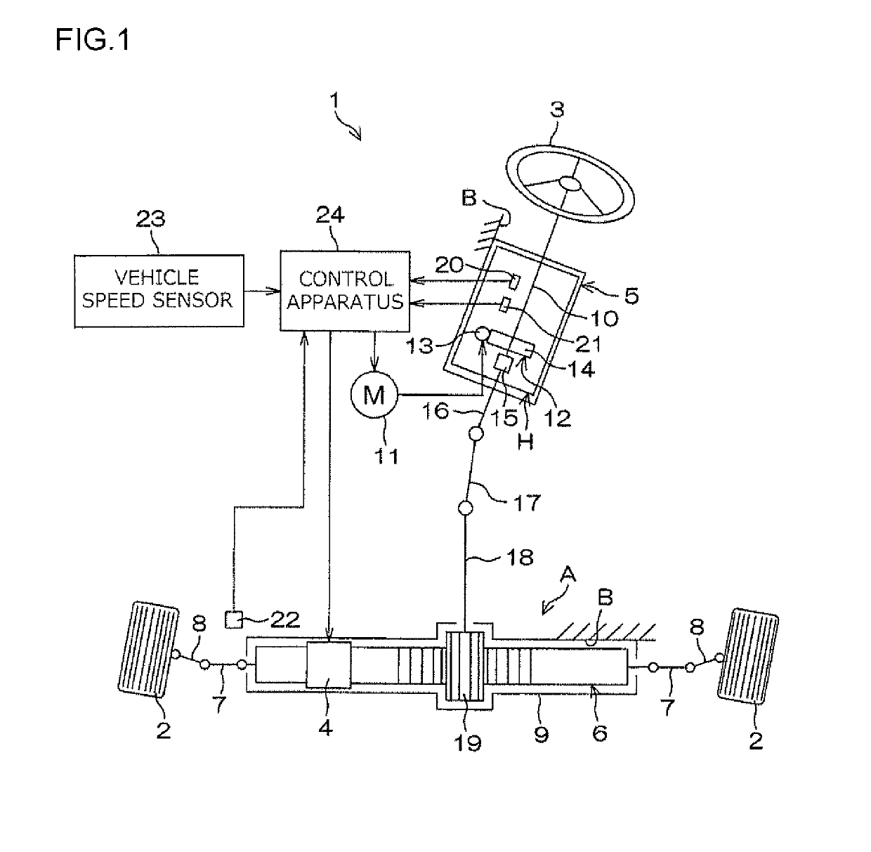
[0026]An embodiment of the invention will be described below in detail with reference to the attached drawings. FIG. 1 is a diagram depicting a general configuration of a steering system 1 according to an embodiment of the invention. The steering system 1 adopts what is called a steer-by-wire system in which a steering member 3 such as a steering wheel is mechanically uncoupled from a steering operation mechanism A allowing steering of steered wheels 2.

[0027]In the steering system 1, an operation of a steering operation actuator 4 is controlled according to a rotating operation of the steering member 3. The operation is converted into linear motion of a steered shaft 6 in a vehicle width direction. The linear motion of the steered shaft 6 is converted into a steering motion of the right and left steered wheels 2 to be steered, thereby turning of the vehicle is achieved. Specifically, the steering operation actuator 4 includes a motor. A driving force of the motor is converted into l...


PUM


Abstract

A steering system includes: a steering shaft to which a steering member is coupled; a worm wheel attached to the steering shaft so as to be rotatable integrally with the steering shaft; a housing that houses the worm wheel; an output shaft that is coaxial with the steering shaft and rotatable relative to the steering shaft and coupled to a steering operation mechanism; and a clutch mechanism that enables and disables transmission of power between the steering shaft and the output shaft. The clutch mechanism is housed and disposed in an internal space in the housing. A solenoid in the clutch mechanism is disposed on the opposite side of the worm wheel in an axial direction from a mechanical portion of the clutch mechanism.

Description

INCORPORATION BY REFERENCE[0001]The disclosure of Japanese Patent Application No. 2015-121122 filed on Jun. 16, 2015 including the specification, drawings and abstract, is incorporated herein by reference in its entirety.BACKGROUND OF THE INVENTION[0002]1. Field of the Invention[0003]The invention relates to a steering system.[0004]2. Description of the Related Art[0005]A steer-by-wire system has been proposed in which a steering member and a steering operation mechanism are not mechanically coupled together and in which a steering angle of a steering wheel is detected by an angle sensor so that a driving force exerted by a steering operation actuator controlled in accordance with a sensor output from the angle sensor is transmitted to the steering operation mechanism (see, for example, Japanese Patent Application Publication No. 2013-132950 (JP 2013-132950 A)). On the other hand, when the steer-by-wire system is mounted in a vehicle, an appropriate measure needs to be taken so that...

Claims


Application Information

Patent Timeline
Patent Type & Authority Patents(United States)
IPC IPC(8): B62D5/04B62D3/04B62D5/00B62D5/24F16D11/00F16D13/00
CPCB62D5/0454B62D3/04B62D5/003F16D13/00B62D5/0409B62D5/24F16D11/00B62D5/043
Inventor SHIINA, AKIHIKO
Owner JTEKT CORP
Why Eureka
Try Eureka