Monitoring rotating machinery using radio frequency probes

Active Publication Date: 2019-05-07
UNIV OF NOTRE DAME DU LAC
View PDF33 Cites 11 Cited by
  • Summary
  • Abstract
  • Description
  • Claims
  • Application Information

AI Technical Summary

Problems solved by technology

Modern turbomachinery is often designed to satisfy a number of difficult operating requirements, including close mechanical tolerances, high temperatures, high pressures, high mechanical stresses, harsh operating environments, etc.

Method used


Image

  • Monitoring rotating machinery using radio frequency probes
  • Monitoring rotating machinery using radio frequency probes
  • Monitoring rotating machinery using radio frequency probes

Examples


Embodiment Construction

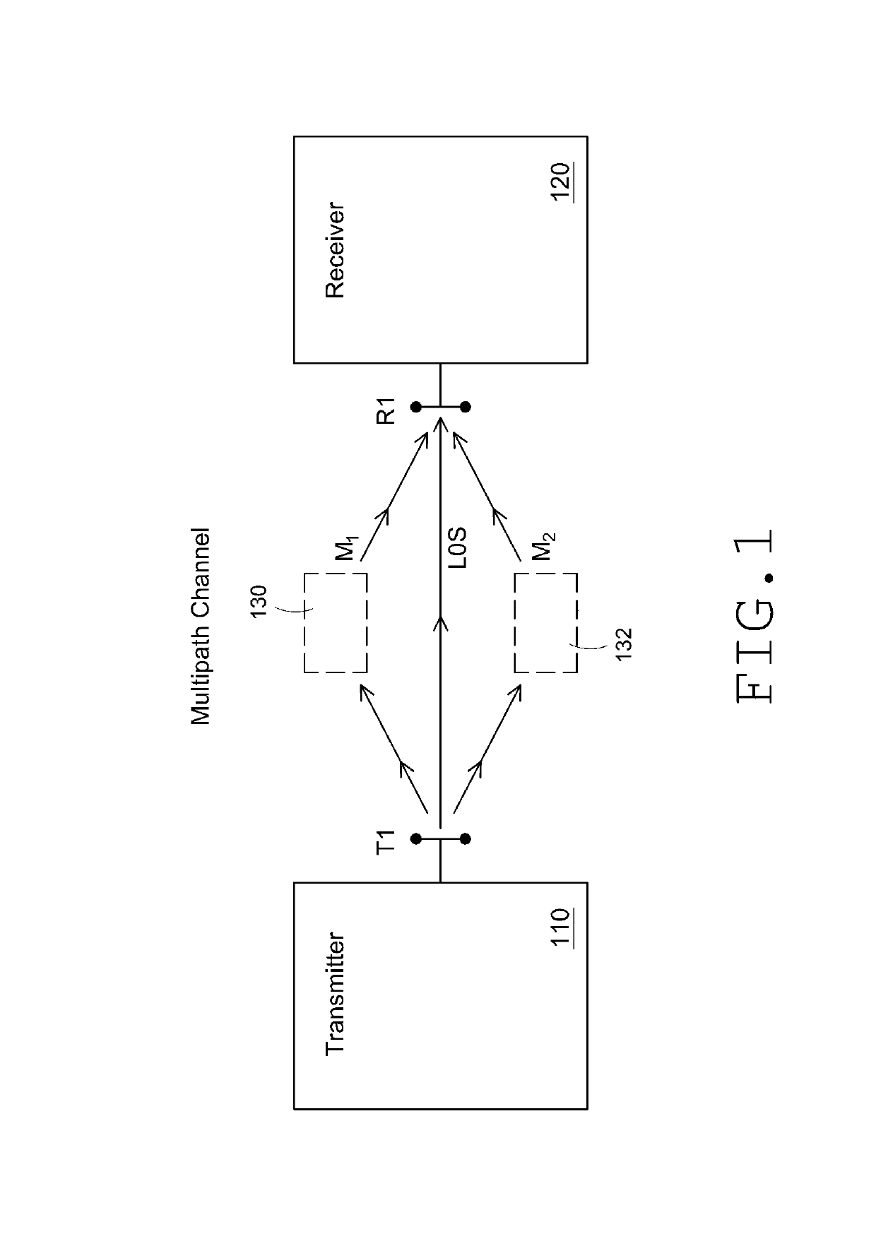
[0027]The systems and methods described herein are useful for analyzing signals that have propagated from a transmitter to a receiver through a frequency-selective channel, such as a multipath channel, in order to determine information about the transmitter, the receiver, and / or the channel (including one or more targets located in the channel). As discussed further herein, the channel can include at least a portion of a piece of rotating machinery, such as turbomachinery. These systems and methods can take advantage of, for example, multipath propagation effects that cause modified versions of a transmitted signal to arrive at the receiver after having traversed the multipath channel. (Such multipath propagation effects are discussed with respect to FIG. 1.) These modified versions of the transmitted signals which are detected at the receiver can be compared with one another and / or with the original transmitted signals themselves in order to determine information about the transmit...


PUM


Abstract

Systems and methods for monitoring rotating machinery are disclosed. Transmitter and receiver antennas can be provided with access to the rotating machinery. At least one receiver signal resulting from at least one transmitter signal that has propagated through a portion of the rotating machinery can be obtained. A first signal pair can be formed from a first receiver signal and a first transmitter signal, or from first and second receiver signals obtained from spatially-separated receiver antennas, or from first and second receiver signals which are attributable to different transmitter signals. Amplitude and phase information of a plurality of frequency components for each signal in the first signal pair can be determined. A set of comparison values for the first signal pair can be determined by comparing respective frequency component phases or respective frequency component amplitudes. A characteristic of the rotating machinery can then be analyzed using the comparison values.

Description

STATEMENT REGARDING FEDERALLY SPONSORED R&D[0001]This invention was made with government support under contract N00014-12-1-0539 awarded by the U.S. Office of Naval Research and under contract 2011-11070800002 from the Central Intelligence Agency.INCORPORATION BY REFERENCE TO ANY PRIORITY APPLICATIONS[0002]Any and all applications for which a foreign or domestic priority claim is identified in the Application Data Sheet as filed with the present application are hereby incorporated by reference under 37 CFR 1.57.BACKGROUND[0003]Field[0004]This disclosure relates generally to systems and methods for monitoring rotating machinery, such as turbomachinery, using signals that have propagated from a transmitter to a receiver through a channel as waves in order to obtain information about the transmitter, the receiver, and / or the channel (including a target, such as turbomachinery equipment, located in the channel). More particularly, this disclosure relates to systems and methods for monit...

Claims


Application Information

Patent Timeline
Patent Type & Authority Patents(United States)
IPC IPC(8): F01D21/00H04B1/40
CPCH04B1/40F01D21/003
Inventor PRATT, THOMAS G.MUELLER, JEFFREY G.KOSSLER, ROBERT D.DODSON, NEILMORRIS, SCOTT C.
Owner UNIV OF NOTRE DAME DU LAC
Why Eureka
Try Eureka